vugie
-
Posts
393 -
Joined
-
Last visited
-
Days Won
32
Content Type
Profiles
Forums
Downloads
Gallery
Everything posted by vugie
-
I'm also trying! But I'm trying to convience damn print head to produce some droplets for me. I'm giving it such a nice waveform and the only thing I get is bzzzzzzz
-
Double click on the error (missing assignment...) and LabVIEW will show you where is the problem. Here you didn't wire anything to tunnels on "False" diagram of Case structure. You may either wire something there or let LabVIEW use default values by right-clicking on tunnel and checking "use default if unwired". Generally if you have tunnel marked as empty rectangle, you'll have error there. [edit] jgcode: mind connection?
-
I'm not clever enough. What does change with 3x2 hips? A ladybird?
-
Good point. Why I didn't find something so obvious? Also when there is more than one source (also broken wire), the rest of sources may be anywhere in the array.
-
I calculated how Laplace transformate of output signal will look like: Y(s)=[Kx+KaKb/(Kc+s)]A(s)-[Ky+Kb/(Kc+s)]B(s)-C(s)+Kd So in time domain somehow modified A signal + somehow modified B signal + some bias has to be equal C signal in order to have 0 output. So as you can see there is no general solution as long as C is not dependent on A and B. If you know something on how A,B,C look like in time (even something very general), some constrains for parameters could be calculated.
-
And mine when I have some boring report to write.
-
And don't save anything on the partition you want to restore files from!
-
But there are situations where such parallel (to load cell) connection makes sense. For example you expect very high forces, but the sensor has very small range. With inter-connection sensor feels only a part of total force and the factor (Fsensor/Ftotal) is equal to ks/(ks+ki), where ks and ki are stiffnesses of sensor and inter-connection respectively. Typically any inter-connection will has much much higher stiffness than any sensor and consequently force felt by sensor will be below its sensitivity. But when ks and ki become comparable it may be usable.
-
It won't be trivial. You have to make sure that only one segment is selected (two neigbouring joints have 0x8 flag set), follow the wire in direction of source to find eventual junctions, follow in opposite direction to find all sink terminals... And remember that the only way to change anything in the wire is to delete it and then recreate.
-
Hard too be sure without strict technical drawing, but it seems that two black parts you want to measure force between are stiffly connected with thin silver disc. Think of load cell as of a spring. Measuring the force is nothing more than measuring deformation of the spring in some way. If spring is not allowed to be deformed you will not measure anything. So when you have a mechanical chain and want to measure force between its two parts, you have to cut the chain in this point and put load cell between connecting INDEPENDENTLY both sides of a cell to respective parts of a chain.
-
No such object as wire segment exist according to my knowledge. Only joints. Segment is only visual representation of connections between joints. Joint may be either bend, junction, end or loose end. From the joint wire may go to up, down, left and right (any combination for junctions, two directions for bends and one for ends). If selected segment of the wire is a connection of given joint, its 4th bit (0x8) is set to 1. Only in this case bits 5th and 6th (0x10 and 0x20) have sense. 0 for 0x10 means that left joint side is selected (if present) and 1 means that right joint side is selected. Similarly for 0x20 bit for up and down respectively. Note that bits 0x10 and 0x20 have not much sense for junctions - where segments may be selected in up to 4 directions. Two bits are simply too less to describe such situation. Two figure out what is the situation with selection for junction you have to follow the wire further to the next bend and read it out from the bend. What if you have few 4-directional junctions in row? I don't know. But gb119, what do you exactly need it for? Is Selected property and then first element of Terms[] property not enough to get a source of selected wire?
-
No need to use IMAQ - Get Image Subset from Graphics&Sound -> Picture Function palette does this. If by "Picture" you mean Picture Control, you have to use Picture to Pixmap first.
-

Hard Drive Serial Number
vugie replied to alexp123's topic in Application Builder, Installers and code distribution
As for volume physical serial number you may use Win32_PhysicalMedia class from Windows Management Instrumentation, but you would have to build your own DLL wrapper in C++ or use MS script engine to get this information (examples for both methods for WMI are provided in above link). Additionally WMI gives you classes (I may be wrong - just found this out) to get virtually any number from hardware (i.e. motherboard serial). But it seems to be little bit tricky to use and works only for XP and above. Alternatively you may use diskid32 freeware tool in manner similar to "dir nothing". Using MAC address for licensing is a joke as changing it is very simple even for not advanced user. IMO optimal way is to use combination of few hardware related serials and obsoleting license only when ALL of them change. -
Hard Drive Serial Number
vugie replied to alexp123's topic in Application Builder, Installers and code distribution
It's 1.30 AM - I would better go sleep... [edit] but string parser should be OS language independent -
Hard Drive Serial Number
vugie replied to alexp123's topic in Application Builder, Installers and code distribution
This method may be simply hooked by creating read-only file nothing.txt where you can put whatever you want. Of course one has to figure out first what and where to create... Anyway, much safer method is GetVolumeInformation function from kernel32.dll (to be used with Call Library Function Node). -
This is not required as: (from documentation)But I guess that gb119 would be more interested in this:
-
Terminal has a property Connected wire . You take a wire and get its Terminals[]. The first terminal in this array is always a source terminal (terminals has also Is source? property) - let's call it STerm. Now you have to go through all GObjects on the same diagram. You have four cases here: GObject is either Control, Constant, Node or FlatSequence. Two former have single Terminal property (according to AQ you can typecast Constant to Control making it one case), two latter have Terminals[] property. So for each GObject of these types you have to go through all its terminals (one or more) comparing their references to STerm. It may appear that node you found is a loop or other structure. In this case if you like to search further for the source you have to specify class of terminal reference to OuterTerminal, take Tunnel property, then its Inside Terminals[] property and recursively go further. In simple form I'm doing something similar here in Generate Objects and Links.vi
-
Any way to downgrade it to 8.2?
-
No problem. [watch] (few other simulations included in this movie) It grew up into quite serious real time dynamics simulator with Euler integration scheme, non-linear spring equations, collision engine, independent display and calculation rates... Few details for those wanting to play little bit (performance is much better than in previous version): Only Nodes and Terminals may be movable (in terms of LV class hierarchy) - so no constants and no flat sequences Masses are proportional to object size and scaled with "Mass ratio" parameter - do not set it to 0 "force factor" scales wires elasticity Damping is applied to wires only (not to bouncing). Very high damping will make wires almost stiff Gravity is in pixels/s^2. y axis points down dt is integration step size in seconds. Fractions of seconds make sense. Smaller is (almost) always better - particularly for collisions fps is display only frame rate Have fun spring-wires2.zip
-
LV2009 Data Value References should be used SPARINGLY
vugie replied to Aristos Queue's topic in Object-Oriented Programming
...and then it suddenly stood up and said: "I'm not waiting for this bloody reference, I'm going back to 8.6" -
Also elasticity of the wires may be dependent on their thickness. Or amount of data they carry I just realized that word "wired" is not the same as "weird", which I really meant...
-
Ages ago in DOS ancient timesthere was a virus called "falling letters":
-
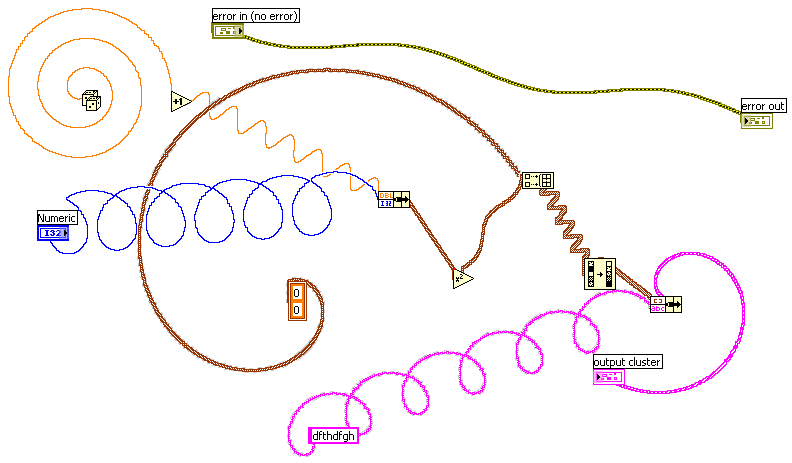
It's just tu pun together some pics from this topic and little bit more... So we already saw that wires may go diagonally: Then that they may have almost any shape: Michael showed us how execution dots propagates on such wires: Link Sources for creating such wires here. Now I'm getting crazy. Sit down, fasten your seat belts, hold your breatch and watch this. Although it does not run too fast (no more than 10 fps on my computer) but Jing slowed it down even more, so in real everything happens much more smoothly. If you would like to play with this: controls or nodes which have labels are fixed to backgroung. Don't change damping too much. Don't put too much objects on BD. Always wire both inner and outer terminals in tunels. Sources attached. spring-wires.zip
-
Done: However cross calculation algorithm slowed it down quite much. And highlight execution drops "bounce" on crossings...

-
Same, as I guess, applies to templates? Functions overloading?