vugie
-
Posts
393 -
Joined
-
Last visited
-
Days Won
32
Content Type
Profiles
Forums
Downloads
Gallery
Everything posted by vugie
-
I'm making wrappers for certain open source library (DLL). It has its own error handling: each time when an error appears special Error() function is called with error number and message as arguments. It looks like that: void Error(int errnum, char *msg){ if (custom error handler defined) custom_error_handler(errnum, msg) else DisplayDialog(errnum,msg); abort();} The problem is that LabVIEW crashes each time library calls Error() function. At first dialog with error number appears (as it should), then after clicking OK windows dialog "application unexpectly quit", everything hangs for a while and LV IDE disappears... I think that abort() is not LV friendly. I compile the library myself, but due to maintenance and licensing issue I don't want to modify its code. I would rather like to create my custom error handler (there is a SetErrorHandler function which gets a pointer to it), which would exit somehow more softly. I'm already able to build another DLL with error handler an to provide its pointer to SetErrorHandler (using GetProcAddress function of Kernel32.dll). But how to exit softly and provide error information up to LV wrapper? Maybe is there a way to compile DLL in such way that abort is more LV friendly? (MSVC Express)
-
What an interesting discussion you started That is also my experience: a question itself causes that I find solution faster
-
Pravin, check carefully the example I referenced in this thread (yours BTW, and on the same topic). BitMan has a routine which realizes exactly what you want.
-
More or less, but better. Because you know better what you have already read, than a stupid machine on the opposite side of the wire. Main forum page, almost at the bottom.
-

Rotation of image array without using NI Vision VI
vugie replied to pravin's topic in Machine Vision and Imaging
Or this one, here on LAVA -
[CR] UI Tools addon: Control class
vugie replied to Francois Normandin's topic in Code Repository (Certified)
BitMan is already packaged and ready to downlad at: -
OT Cat, did you hear of SWIG? It is able to create XML with pure information about data structures and functions out of a header file.
-
Here is the latest version I published (I hope). The current version (0.3) is completly rewritten (object oriented) and LabVIEW part is mostly done (parsing and template based script generation). The missing thing is good template and this is blocking me from further development, because it requires ActionScript programming skills which I have no time to learn (which is more complicated considering that I don't have Flash IDE and I use only OS tools). So if anybody here knows what is going on inside Flash, I'm open for cooperation. This would help to unfreeze this project. Of course if community needs something like this in days of snippets... VIpreVIEW-0.2.1.zip
-
Need a small font for icons or other details?
vugie replied to Aristos Queue's topic in User Interface
In fact, very nice. However it only works for LCD screens, and not all of them - those with RGB-RGB pixel scheme (most of LCD screens) -
If the only goal is to let the user see the line, you may make the box semi-transparent... If it is not the case you have to calculate proper path by yourself.
-
Look carefully what are you doing: for each mouse click you get cluster of 3 coordinates, make a SINGLE element array of cluster of 3 coordinates (?), interpolate over this 1-element array (I don't know for how many samples you do it, but for default - linear interpolation, you'll get 1 usable sample and the rest will be Inf), and then create line out of it. So you create ONE line object, made of ONE point for EACH mouse click... Instead you should create a line object with null mesh outside the loop, keep its reference and at each mouse click add point to the buffer (kept in shift register for example), and UPDATE mesh of the line object out of WHOLE buffer. BTW, You use Mouse Down event. It is better to use Mouse Up, because Mouse Down fires continuously as button is hold.
-
It is very specific problem for spatial interpolation, because of nature of source data. It is hard to put any general algorithm, however you may check for Kriging or Natural Neighbor Interpolation. But I would rather develop custom algorithm based on known geometrical relations between 2D sections dipped in 3D space. [EDIT]] I think that you may be interested in this
-
As for interpolation it would be something like this: For creating the buffer you may use i.e. Functional Global

-
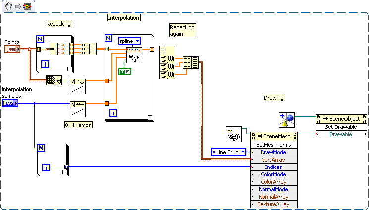
It depends on how exactly you want to represent the curve. If it is ok to connect your points with straight lines you may feed directly their coordinates to mesh primitive with "line strip" mode. If you want more smooth curve, you have to do interpolation - this is as simple as 1D interpolation separately for each coordinate. I assume that you know the order of your points, in other case you have to sort them somehow before and it may be more complicated than interpolation.
-
You said that you track for (x,y,z) coordinates of the probe. Does it mean that your 2D US images are always parallel to each other? If it is not the case you have to track also orientation of the probe. And I think you should do it if the probe is being moved manually (it is rather impossible to manually move such a probe keeping 3 orientation angles with certain precision). Next point - what is the nature of 3D information you want to calculate from subsequent frames? Do you want to have 3D volumetric image, reconstruction of surface of some object, set of iso-surfaces? Not in every case point cloud approach is really necessary. I.e. for volumetric image I would rather use some interpolation technique (if frames are dense enough). And volumetric image is good starting point for any surface extraction technique as there are many well established algorithms for it.
-
As I understand it: You have a movable object called "3D Image" on which you know local coordinates of several points. Are you tracking global coordinates of one of these points but you don't know which one exactly? What is pairing for? Please describe your system in more detailed way, possibly with pictures...
-
I recently used TCamRemote ActiveX library, which is an abstraction layer around Canon SDKs. Works very well (with one small issue) and it is really very well documented.
-
I'm still for something little bit more controversial for the back. I.e. modification of my last year proposition: Or something about the rest of private properties, or Xnodes, or this 1% of icon editor which is not open source (or its license which is ???), or questionable performance of InPlace structure, or any other hot topic. Let's show that we are independent!
-
pickpoint method malfunctioning after set rotation use
vugie replied to Trin's topic in LabVIEW General
I didn't run your VIs, but my guess is that you get right coordinates - coordinates for rotated object. Because you place a sensor as a child of main object, its translation is relative to this object. Pick Point gives you absolute coordinates. You decided to use object transformation to mimic camera behavior. This approach has both advantages and drawbacks. The drawback is that you have to apply inverse transformation to each absolute point you get from Pick Point in order to have its relative location. Inverse transformation is easy to calculate: it is still 4x4 matrix with 3x3 rotation component, 3x1 translation component, 3 zeros and 1. You simply has to transpose rotation component (inverse matrix for rotation matrix is always equal to its transposition) and negate translation component. But I advice you rather to use camera as a camera (and either Setup Camera method or changing modelview matrix). Things will be much simpler then. -
That part is OK, but in main loop you read modelview matrix, calculate camera vectors and use them with "Setup Camera" not modifying them at all. VIDEO By pressing Shift magnifying glass appears. By pressing Ctrl panning cross appears.
-
Frustum defines field of view, but far and near planes are not for zoom - they are for clipping objects behind them. For orthographic projection modifying the rest of parameters may work like zoom, but the effect will be dependent on control proportions - I wouldn't recommend it. BTW, did you try shift-dragging on the control (with perspective projection)? You do strange things in your VIs... i.e. reading modelview, extracting orientation and applying it again without modification... You should relate values of camera movement to size of your object, to be sure that steps you are making are not 100x higher than the object. If you move camera to some absolute position/orientation, turn off native controller, bacause any click will be unpredictable. And assign some default values to y controls, because feeding zeros to Delanulay method crashes LabVIEW (brrrr, I had some calculations ongoing... )
-
It applies only to LV native controller. You can change its mode either with control's context menu or with respective property. You can still program your own camera behavior and user interaction. In the other topic (I guess that both refer to the same project) you wrote that you want to catch user clicks on the control. Because native controller bases on left mouse click it would be good to turn it off and implement your own (basing on buttons, touchpad-like area, right-clicking, clicking with modifier, accelerometer based device or anything you want). The question is what projection do you use - perspective or orthographic. If the first you can simply use camera position as a zoom. For orthographic projection moving camera along viewing direction has no effect - you have to use projection matrix (from respective property), specifically first two components of its diagonal. You may use this method for perspective projection as well. Direction is an unit vector pointing along camera's optical axis. in terms of Setup Camera method direction = ( target - position ) / ( | target - position | )
-
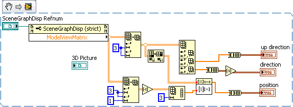
Ok - as usual it was lack of knowledge, not a bug... Here is the method to get camera vectors from modelview matrix: As a target for "Setup Camera" [(direction*any_scalar)+position] may be used.
-
If you set Camera Controller to "None", current camera position is that one you recently set I tried to prepare simple example to show how to convert modelview matrix to vectors usable for Setup Camera method, but I found strange issue, which looks like a bug... so I have to dig a little bit more.
-
Modelview is 4x4 matrix which consist of: - 3x3 rotation matrix in upper left corner - 3x1 translation vector at the right side - 1 in bottom right corner - zeros in the rest (1x3) try googling "modelview matrix" - this term is exactly the same as in OpenGL I think that most convenient method would be to use Setup Camera method for translation as well (storing current camera position and orientation and blocking native LV controller)