EricLarsen
-
Posts
88 -
Joined
-
Last visited
-
Days Won
2
Content Type
Profiles
Forums
Downloads
Gallery
Everything posted by EricLarsen
-
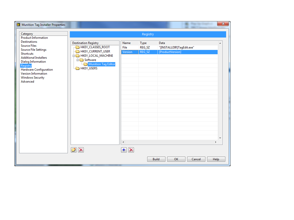
This is a follow up question to this thread: http://lavag.org/topic/16923-get-custom-application-install-directory/ Is there an easy way to get the executable version during installaltion? There is a token [ProductVersion] that appears to return the version of the installer build, but I'd really like to get the version of the .exe file. Can't find anything that can do that.

-
That exactly what I need. Thanks!
-
Is there an easy way to get the destination directory the user selects during custom executable installation? There are probably some ways to get it using a post installation application, but it seems like a cludge. Ideally what I'd like to do is create a registry entry during installation that records the installation directory.
-
Just for future reference, for 0-100 degC conditions I've used many of these: http://www.digikey.com/catalog/en/partgroup/ad592/10680 Ridiculously cheap and ridiculously accurate. They are current sourcing, so we've used them with wire distances of several hundred feet with no noise or drop in accuracy. They do requre a voltage exication source, typically 24VDc. Wire them in series with a high precision resistor (usually 10k, 0.01%) near the data logger to convert the current to a voltage. Depending on what accuracy you'd need, the total cost of sensor + resistor is about 10-20 bucks.
-
Ah, I get it now. Yep, creating an instance of a concrete class did it. My wrapper code appears to be working. Thanks! I'm up to 2 whole days of programming .NET. Time to add .NET programmer to my resume.
-
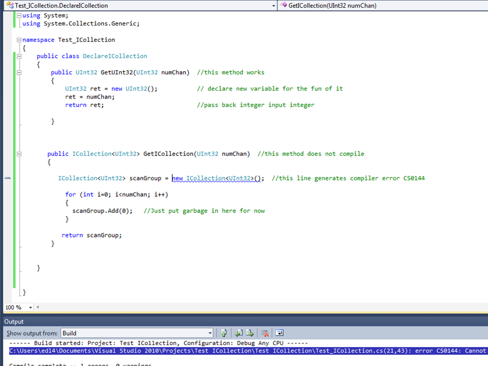
After a 20 year hiatus, I'm back to writing text code again. Not just any text code, but C# .NET assemblies. After about a day and a half of googling and self teaching, I've hit the wall. I've got a .NET assembly that was provided by a manufacturer that controls some hardware. We are calling the higher level .NET functions from Labview and they work. But we aren't getting acceptable performance for the high level calls, so we are trying to drill down into the lower level calls. One of the .NET methods requires an ICollection<T> input, there in this case T is a channel object that is created elsewhere. The ICollection function is described the in the MSDN article: http://msdn.microsoft.com/en-us/library/92t2ye13 For reasons I don't really understand, Labview doesn't apparently support a constructor to ICollection. Something about Labivew not supporting calls to .NET generics, but I'd be lying if I said I understood that. But it seems like it should be possible to create a .NET assembly that creates a reference to an ICollection .NET object that can be passed to Labview. But I can't get it to work. I've written a simple program that contains two methods. The first method GetUInt32 simply returns an input integer and was written as a test to see if I could write and assembly and call it from Labview. It works great. The second method, GetICollection, is a test case to create a collection of UInt32 integers. Should be really simple, but it generates a compiler error. I suspect I'm doing something really basic incorrectly, but I'm at a loss to understand what. Can someone point me in the correct direction?
-
The vision package should be able to do that. I think you’re looking at a fairly standard particle counting algorithm, which in theory is pretty easy. But like everything, the devil is in the details. The key to any vision system is in consistent lighting conditions. That might be harder to achieve in a building environment. What specifically is your application? Are you looking at huge crowds of people, or just an occasional individual? Is this an office building, sports stadium, or single room? Is the camera already in place, or can you position it and control the lighting? All of these answers will have an impact on your solution. The easiest thing might be to get a cheap USB camera, download the evaluation version of the Vision Toolkit, and play.
-
Please help, Convert this string format to number
EricLarsen replied to lovemachinez's topic in LabVIEW General
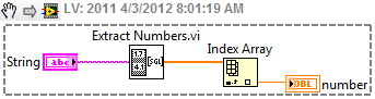
There is a vi in the examples called Extract Numbers.vi. It's perfect for this application. It takes a string as an input and converts it to an array of numbers. Then you simply index the array to extract the number you need. It's really useful when your string contains more than one number.
-
Wait for front panel activity and remote panels
EricLarsen replied to MarkCG's topic in User Interface
You can use network shared variables to do the same thing. A little eaiser than TCP/IP strings. I usually a string variable called Command to send messages to the target, then a string variable called Status to send messages from the RT to the Host. -
I think you can do what you want using VISA. Check out this article: http://digital.ni.com/public.nsf/allkb/B937AC4D8664E37886257206000551CB
-
GPIB controlled Fluke timeout errors
EricLarsen replied to longzoo's topic in Remote Control, Monitoring and the Internet
The first thing to try is disable automatic error handling in your sub-vi. Wire the error cluster out and check it in your calling vi. If the instrument reports an error, try calling this vi again until you get no error. But like you said, your best bet is to eliminate the source of the error. I've found with instruments like this it's best to limit the number of commands sent to it. It just seems like you can overwhelm it and eventually scramble its brains. I'm not familair with this instruement, but do you need to send the set up commands every time? The trigger and sample count commands may only need to be sent once to set up the instrument, then just send the fetch command every time you need a reading. Also, putting a slight delay (50ms?) between commands can help, too. It gives the unit time to play catch up. It may take some trial and error to make it preform like you want. -
Sounds like you still have one of the parameters set wrong. The values shown in the manual are probably the default values for the HH506R, it's possible they have been changed. Try different values, starting with BAUD. You might get lucky.
-
Solar Tracking using Labview and camera
EricLarsen replied to dcg's topic in Machine Vision and Imaging
If this is a project to position solar arrays, do you really need to measure the sun's location? If you know the date, time of day and lat/long, it would be much easier to calculate position instead of trying to develop the hardware to measure location. If you're set on measuring location, like Tim said, take lots of pictures of your sun dial at various times of day and under various brightness conditions and start developing the algorithm using those. One thing your going to find challenging is the change in lighting conditons. When you start doing vision analysis, you'll find very quickly that consistent lighting is the most important part of capturing images. Since you're going to use natural lighting, as the brightness of the sun changes during the day, or due to cloud cover or seasonal changes, your lighting is going to very drastically and you'll need to be very clever in how you do your analysis. You will probably have to develop some kind of thresholding routine that changes as your lighting conditions change. Start by looking for the cross-hair shown in your picture. Set the threshold on your image so you can see that distinctly, then start looking for your sun dial shadow. You might have to make an assumption about where is should be based on time of day, and change the image threshold until you can find it. -
Can't see decimals on tags - ni opc server/client
EricLarsen replied to dsasorin's topic in Hardware
A single mod bus register is a 16 bit register and can only contain integer values. Therefore, your instruement is probably rounding off the floating point value to an integer before storing it. The typical way for an instrument to pass floating point values is to break up a 32 bit floating point number into 2 consecutive 16 bit registers. You can then read the two registers and combine the values using the method described here: http://digital.ni.com/public.nsf/allkb/2462D01074BDB1A886256D9600506763 You'll have to configure your power analyzer to pass the floating point value this way. Check the documentation to see if this is possible. -
I'm trying to read some data from a Modbus instrument using the I/O server in DSC over TCP. The instrument writes a 32 bit floating point value into 2 16 bit registers. If I read the two 16 registers separately, then combine and typecast them I get the correct value. However, if I rely on the I/O server to read the floating point value directly, it gets a slightly incorrect result. For example, my instrument wrote the value 34.80 into the two registers 30123 and 30124. If I read each register (300123,300124) separately and combine the values, I get the correct 34.80 result . However, if I read the register F300124 I get the result of 34.85. This is consistent; I always get a value that is about 0.05 to 0.10 off. At first I thought that was the incorrect floating point address, so I tried reading F300123, but that returns a result on the order of 6.7e-6. I'm never tried to use DSC to interface to modbus, so I'm probably missing something obvious, but I'm stumped. Any ideas?
-
In the space of one paragraph you have explained about a decade’s worth of random mysterious TCP/IP errors! So when the error uses the term "peer", is that referring to the TCP/IP connection on the local machine? That error description makes it sound like the remote machine was actively closing the connection.
-
It was nothing like that! Actually I was using the DSC to generate a dynamic event every time the alarm status of a shared variable changed. Normally that would be about 1 event an hour. Unbeknowst to me, the option to generate an event every time the shared variable value changed had been checked on several dozen of those shared variables. I don't remember checking that option, but it must have been me. So when our process was in a rapidly changing state, it generated lots and lots of dynamic events. But since the problem wasn't actually in my code, but in the shared variable configuration, I barked up the wrong tree for months trying to track this down. Great info, thanks!
-
So I just fixed was is probably the nastiest code bug I've ever had in my career. I had an event structure in a user interface that would run all fat and happy for weeks, and then it would get in a mode where it would start taking several minutes to process a front panel input. It would be in this mode for about an hour, then return to normal function again. This bug drove me and my users crazy for months. Yesterday I finally figured it out. The event structure was processing both front panel events and programmaticaly fired events. Due to a programming bug on my part, sometimes the programic events would fire 100s of times more often then I'd intended. Most of the time, the user interface could keep up with the extra events so I'd never noticed anything was wrong. But if the user performed a ceritan sequence of front panel actions, it would cause a slight bottleneck in the event structure. This would cause a flood of unprocessed programmic events to stack up, slowing everything down. After a while, the event structure would catch back up and everying would be fine again. This was one of those "perfect storm" bugs where a lot of things had to happen in the right order for things to go wrong. I'm pretty happy I figured it out. So this led me to the question, is there anyway to determine how many unprocessed events are waiting in an event queue? I think this question had come up before, but I couldn't find any threads that answered it.
-
Yep, that's part of what makes this an interesting problem. A back of the evelope calculation indicates that keeping the thermal mass of the TC small relative to the thermal mass of the sample could give good results. As the TC/sample ratio increases, the TC itself starts effecting the measurement. You might be able to account for in post-process analysis if you know the masses well enough. Good idea. I didn't realize they has such fast response times. That's worth looking into. Thanks!
-
I had a customer come to me with an interesting problem and was hoping somebody here has experience with a similar issue. My customer has a thermal process that has a very high temperature transient, on the order of 500 degC/second. They are using a conventional thermocouple DAQ system, in this case an SCXI thermocouple module (not sure which one). But the SCXI system has built in lowpass filters on the order of 4Hz, so they are missing the transients. Most TC signal conditioning modules have lowpass filters and I've never tried to read a TC at a higher rate. Has anybody ever tried to read a TC at 1-2 kHz with a millivolt input DAQ card? We have a TC welding system that can weld very fine gauge TCs directly to the sample which should minimize temperature lag. It seems like by using a conventional DAQ card and appropriate cold junction compensation there isn't any reason we shouldn't be able to read this fast, but are there any issues to be aware of before heading down this path?
-
At my company, we don't get administrative rights to our office computers (fortunately, this does not apply to our laboratory machines, YET). Anyway, when I install software on my office machine, I have to call IT, who can remotely log in to my computer and temporarily elevate my account to administrative rights so I can do my own installs. It used to be that they would elevate rights then leave you alone and trust you to reboot to return to standard user rights. But my last install, I was informed that they would have to stay remotely logged in to watch my actions to make sure I wasn't doing something bad. When I informed them that the NI installs take hours (4+ in the this case), there was dead silence on the other end. They very quickly developed a new procedure where they can grant exemptions to the new rule.
-
When serial communication doesn't work, the first suspect is always the cable. Double and triple check you have the connections done right. But the fact that you are getting some data back might indicate the connections are correct, but triple check them anyway. I've used quite a few 1179As in the past and have had really good luck with them. Somewhere around I have a cable diagram, if I can scrounge that up I'll send that to you. In the meantime, here is a small library of VIs I wrote to communicate with the 1179As. Sorry, they aren't documented very well, but they should be pretty self-explanitory. Just open up MKS 1179A Tree.vi for access to the top level Vis. Each 1179 has to be assigned a unique address, and I don't remember how to do that, but you'll need to know the address to communicate with the proper unit. It seems to me that all units start with a default address (255?). Something like that. You then use the change address VI to set it the address you want. You also need to calculate the proper checksum to transmit to the instrument, my code will show you how that's done. The Wink.vi command is a very handy utility to run. It will cause an LED on the MFC to blink, which will tell you if you have communication established. MKS 1179A.zip
-
Should elimiate the problem? Maybe. Does it? I wouldn't count on it. It still sounds to me like a cabling issue. If you have a null modem, try it. But null modems don't always solve the problem, especially if they are 25 pin null modems and you are using adapters go to 9 pin connectors. Often times that combination disrupts the ground connection. If you can easily swap pins 2 and 3, that's worth a shot. But I really encourage you to get a break out box.
-
Exactly. The first thing to check when using RS-232 is the cable itself. Was the cable provided by the laser manufacturer? If not, is it one you made yourself? There is no such thing as a "standard" RS-232 cable. Just because a cable worked on one instrument doesn't mean it will work on the next. At a minumum, try swapping pins 2 and 3. Sometimes that will work. The better option is to get a good RS-232 breakout box. If you spend any time at all in the serial world, that will save you hours of headaches.
-
Which version of Excel are you using? I found with Excel 2007 it worked fine if the I gave the copy an extension of .xlsx