Jerzy Tarasiuk
-
Posts
22 -
Joined
-
Last visited
Content Type
Profiles
Forums
Downloads
Gallery
Everything posted by Jerzy Tarasiuk
-
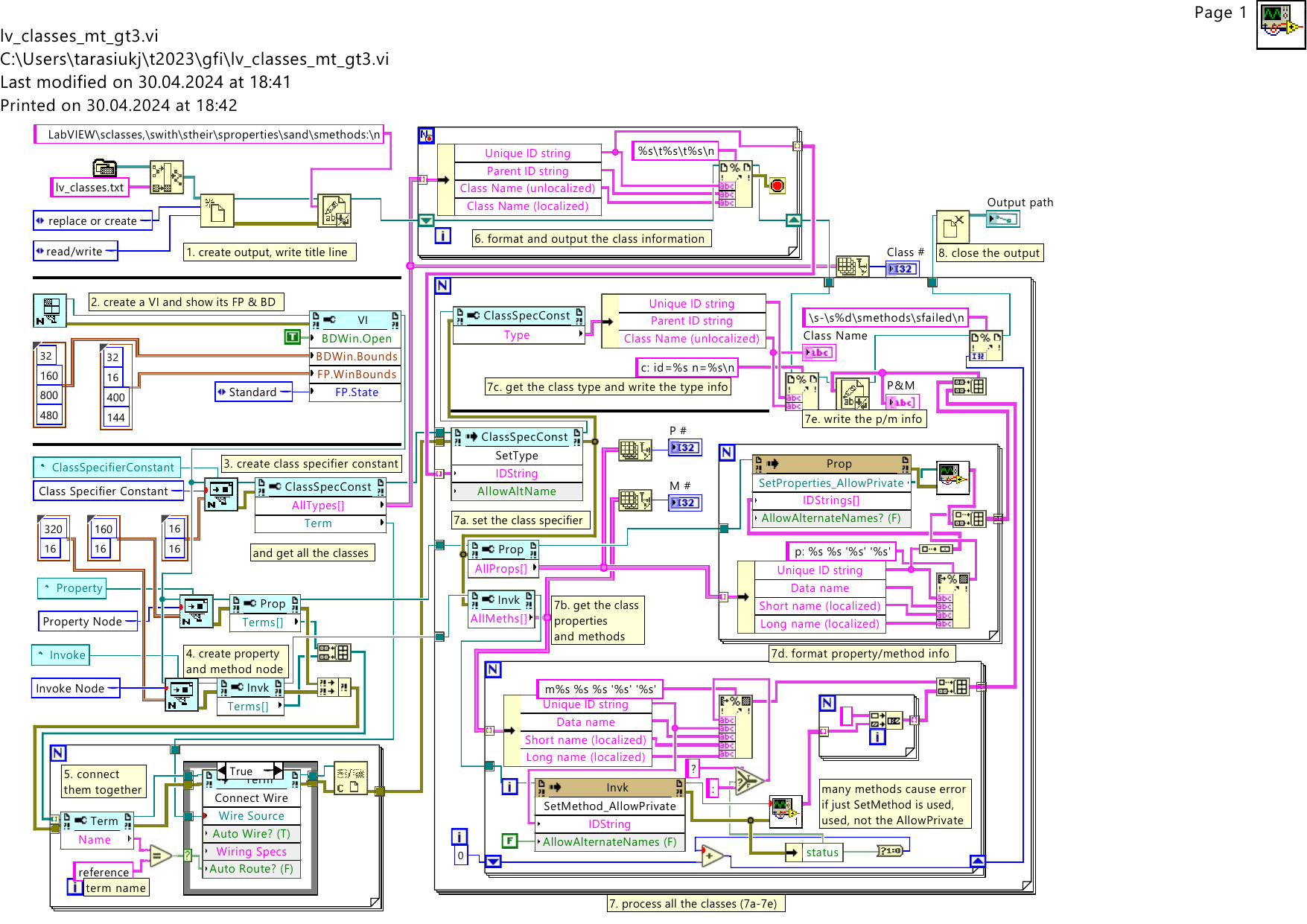
Hi, I made a Tcl script which compresses the property/method information for classes by removing everything inherited from a parent class (this reduces the file size to 18 304 lines); also, I selected classes suitable for FPGA VI - now the text file is below 7 000 lines, and I see no method or property duplicated there. For full class set, 163 methods for VI-like classes weren't reduced because VI class used type LVObjVI and its children used LVObjUnknown; and some properties weren't reduced bacause a child has their access configured differently from its parent, like for both the property was read/write, but the default direction was different (this affects properties: 225 AutoLog.Path, 226 AutoLog.AtFinish, 227 AutoLog.PrintAtFinish, 242 Def Err Handling, 283 AutoPreallocate, 634640e Value, 6346410 DefVal, 6346411 Val(Sgnl), 23f44800 Name, 5436bc00 Texture Generator Mode, 5436bc01 Texture Generator S Plane, 5436bc02 Texture Generator T Plane, 7c86e800 TypeClass, 7c86e80a Value, 7c86e811 UserData). lvc_tree.tcl is the script which can be run on the large (over 4MB) file in the lv_classes.zip I posted on May 18th; the 56kB text file is already "compressed". I found 8 more classes used in FPGA VI-s - they aren't in the file: EIONode, EIOPropertyNode, EIOMethodNode, EIOGrowableMethodNode, LocalResourceManager, niFpgaContainer, nifxpmath_Interpret, niFpgaIPINode. fpga-cl-known-xf.txt lvc_tree.tcl
-
Hello. I found my program lists (to a text file) a similar info that is shown by "All Methods and Properties.vi" - likely something was added since creating the VI - an excerpt from XNode property list: p: 632a804 Width 'Area Width' 'Bounds:Area Width' r: Width (U32) p: 632a817 DependNames 'DependNames' 'Dependencies:Found Dependency Names' r: DependNames (Array) p: 632a816 DependPaths 'DependPaths' 'Dependencies:Found Dependency Paths' r: DependPaths (Array) p: 632a815 MissingNames 'MissingNames' 'Dependencies:Missing Dependency Names' r: MissingNames (Array) p: 632a814 MissingPaths 'MissingPaths' 'Dependencies:Missing Dependency Paths' r: MissingPaths (Array) p: 632a808 GrpMbrRefs[] 'GrpMbrRefs[]' 'Group Member Refs[]' r: GrpMbrRefs[] (Array) The attached ZIP contains the the program, the entire file produced by my program for LabVIEW 2018, and more. The file lists all LabVIEW classes found (287) and is over 100 000 lines long (it can be made much shorted by omitting properties/method inherited from parent of each class, but till now I didn't manage to perform the compression). Class properties and methods information format: 😄 (class info) p: (property info) (t): (terminal info) m: (method info) (t): (terminal info) For property, the (t) may be "r", "w", "r+", "w+", specifying read or write mode, and capability to change (e.g. "r+" means read that can be changed to write, "w" means write-only). For method, the (t) is either "i" or "o", specifying input (host to method), or output (to host) terminal; note some terminals have empty names. The file from the program contains 2468 different properties (i.e. w/ different names), and 1168 different methods. Its name "lv_classes+pmt.txt" stands for "LabVIEW classes + Property and Method Terminals". lv_classes.zip

-
Linux has also a nice tool named "strings". Using these together: strings some.vi | grep \\.vi can produce an output like: !eio_Utilities_GetNonAliasNames.viPTH0 EIO API!eio_Utilities_GetNonAliasNames.vi EIOPlaceDownEIOPropertyNode.vi EIOPlaceDownEIOPropertyNode.vi EIOPlaceDownEIOMethodNode.vi EIOPlaceDownEIOMethodNode.vi Get Type Information.vi Get Type Information.vi Get Type Information.vi EIOPlaceDownEIOPropertyNode.vi EIOPlaceDownEIOMethodNode.vi !eio_Utilities_GetNonAliasNames.viPTH0 EIOPlaceDownEIOMethodNode.vi EIOPlaceDownEIOMethodNode.vi Get Type Information.vi Get Type Information.vi EIOPlaceDownEIOPropertyNode.vi EIOPlaceDownEIOPropertyNode.vi !eio_Utilities_GetNonAliasNames.viPTH0 EIO API!eio_Utilities_GetNonAliasNames.vi some.vi The "strings" tool on Ubuntu 18.04 is in a "binutils" package.
-
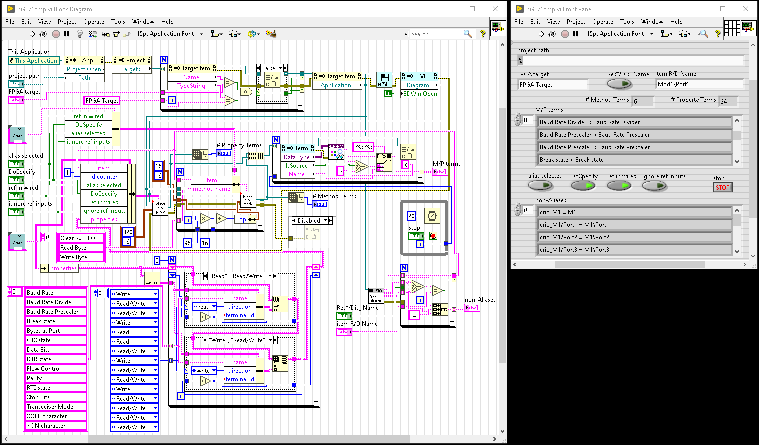
 Some additions: the name ni9871cmp is an abbreviation from NI9871 Create Methods and Properties. when looking for a way to create them, I attempter to use "pylabview" https://github.com/mefistotelis/pylabview to examine VI-s created manually and with scripting and to find their differences; first of all, the "pylabview" is said to be for LabVIEW 2014 - in fact, it couldn't handle VI-s from the LabVIEW 2018 I am using, and it couldn't handle VI-s saved for older LabVIEW versions until I specified as old as 2011; even then, when I used the pylabview to extract contents of a VI containing a valid serial port Method or Property, none of text files produced contained the port name - I found the port name in a binary file only, and it contained UUID-s in "{}", with ">>" as a separator, like "Mod1.{uuid1}>>Port2.{uuid2}" - and I found this all must be exactly the same for the port to be recognized - when I put exactly this string in the alue used for port specification, the scripting produced valid Methods and Properties; then I started to look for a function that can get such a string from my project...
 -
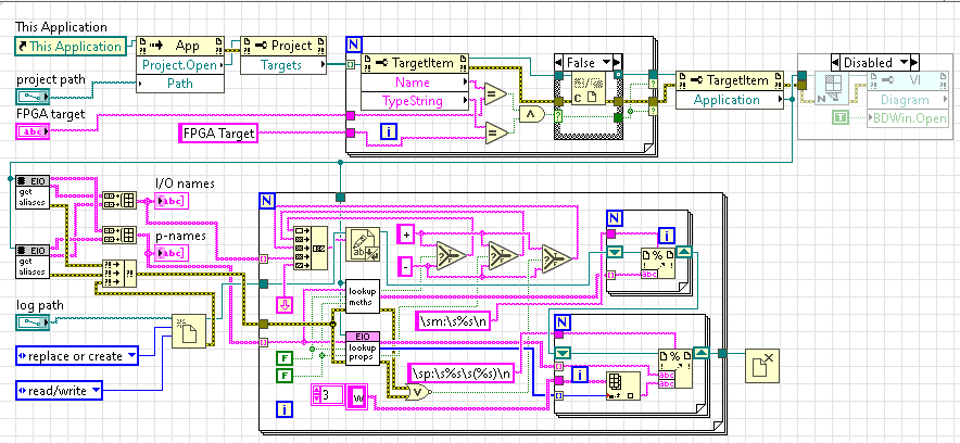
Yet another program: list I/O names and methods/properties available for each of them. Inputs for the VI: LabVIEW project path, FPGA target name, log path (for writing the info). A sample of I/O name lines from the log: These '+'-es at the beginning of each line tell that looking for methods/properties of the I/O item found the item and no error resulted from the operation (each '+' has a different meaning, but I was getting +++ only). First 10 names have no leading '/' - they were found as non-alias names, all remaining - as alias names. Here crio_Module5 is NI9476, it has a "Check Output Status" method and 3 properties (these properties common to all C-Modules, and they are read-only, it is shown by '(R)'); crio_Mod6 is NI9205, it has 4 methods and 15 properties; crio_Mod1 is NI9871, it has 3 properties and no methods; its Port1 has 3 methods and several properties, some are read-only (R), some write-only (W), some bidirectional default-write (Bw), a (Br) would mean bidirectional default-read. Here crio_Mod7 is NI9208, it has 4 properties (an additional is "Conversion Time"). Then alias I/O items follow: "Chassis Temperature" can be read, "Sleep" can be read and written, as well as "System Reset" and "USER FPGA LED", "USER Push Button" can be read, and "Scan Clock" has 2 methods and 2 properties. Here crio_M3 is NI9477, its DO0 signal can be read and written, as well as DO0 signal of crio_Module5 (NI9476); crio_M4 is NI9425, its DI signal can be read, as well as crio_Mod6 (NI9205) AI0 and AI31 signals. The NI9205 has also Trig signal (read-only), DI0 signal (read-only), DO0 signal (write-only). And finally few CLIP signals: "/v1/SignalList/a.b0" is "a.b0" of CLIP "v1" (write-only), "/v1/SignalList/aw" is "aw" signal of the CLIP (read-only). Attached: a VI used to produce the list and its BD picture. io_names_list2l.vi
-
Hi, seems I found a solution. The program should do the following: use Invoke Node for This Application constant to open a project with an FPGA target; use Property Node on the project ref to get targets; look for a matching FPGA target (in my example I also compare target name, so it can handle a project with many FPGA targets if it happens), closing the other target refs; use Property Node on the selected target ref to get its Application ref; create (or open) a VI for the Application, open its BD window, gets its BD ref; (the above action is in the upper line of my VI) use eio_Utilities_GetNonAliasNames.vi on the Application to get names to be used: - "persistent names" output gives names (array of strings) that can be used, - "resource names" and "display names" (arrays of strings) can be used to find an element in the "persistent names" - choose e.g. Mod1\Port3 in display names, and use its index on the "persistent names" to get required persistent name; the persistent name is to be used as "item" for EIOPlaceDownEIOMethodNode.vi and for EIOPlaceDownEIOPropertyNode.vi - the "item" is in "State" cluster; few other elements of the "State" cluster, common for these both "Place"-s, are: "alias selected", "DoSpecify", "ref in wired", "ignore ref inputs"; the "alias selected" must be False, the "ref in wired" must be True; do the other matter? I don't know; making a Method needs also a "method name" to be set, valid methods for an NI9871 serial port are "Clear Rx FIFO", "Read Byte", "Write Byte"; for making a property I specified "id counter" = 1 (is it needed? I don't know), and of course the "properties" - an array of clusters, in each of them I set: "name" (string), "direction" (enum, I used read or write), "terminal id" (int); each "Place" needs also Diagram (I used the BD ref), context (= Application ref), and "Position" (a cluster containing left-top corner coordinates); each "Place" returns a "Terms[]" - an array of terminals - I show some info on them. Attached files: a picture w/ BD and FP, a PDF containing the BD, the VI (LabVIEW 2018). ni9871cmp.pdf ni9871cmp.vi
-
I need a program in FPGA to control a hardware, without mediation of RT part - and I plan to use LabVIEW for the FPGA only. Because of this, there is no place for using VISA. I want to have the same code for each serial port - they are to be configured differently, but the configuration should be passed as data to the code that is to set it to these ports. FPGA has access to these ports (the VISA would access them via FPGA), but I don't know how to place a port name in LabVIEW - the only way I know is to select manually the port resource for each Property and Method used to access the port. And I don't know how can I programmatically verify that the correct port resource is selected in each place, as I have no way to read it.
-
Hello, I discovered a solution just today evening (around 20 of local time, now here is 22:28). Use EIOPlaceDownEIONode.vi to make an empty EIO Node; then use EIONode_ScriptAddChannel.vi to add channel(s); if there is one channel only, use also EIONode_ScriptModifyChannel.vi to set the channel - after the Add the terminal has Void data type, the Modify causes it to get the correct data type. When more than one channel is Add-ed, the Modify is unnecessary - the data type is set correctly for all channels. I hasn't investigate this in detail: seems "direction" can be specified as "none" unless more than one direction is valid (as for e.g. Digital Out signals); and possibly using Add (without specifying channel parameters) to add as many channels as needed, then Modify to set their parameters can be used, too. I attempted to find a way to delete a channel from EIO Node (by "Delete" Invoke Node on a terminal), no success.
-
Hello. I want to create a VI for each serial port that will configure the port according to configuration data sent to the VI - this requires many connections inside the VI and results in many possibilities of mistakes in these connections if they are to be done manually. I would like to avoid these mistakes. Currently, I can use Scripting to create Method Nodes and Property Nodes needed, then request setting the serial port in them manually, then use Scripting to create connections, and finally report all connections to a text file for verification. But I neither know how to set the serial port in these nodes using Scripting, nor I know how to get these settings for verification. BTW: is it possible that two Property Nodes for a serial port look identically (have the same port in their header lines, the same elements, data types for these elements are shown by the same colors...), but have different functionality (e.g. something hidden was created in one of these nodes while editing it)?
-
Hello. Seems none of these examples show how to use VI Scripting to create an FPGA VI that accesses NI-987x serial port...
-
Hello. My aim is to access these ports directly from FPGA program, without VISA and drivers that are in RT part. It is possible when the program is edited manually in LabVIEW development environment.
-
Hello, Rolf. Thank you for the time you are spending on it. My problem is: I can create - using Scripting - a serial port Method Node (with EIOPlaceDownEIOMethodNode.vi, for any of 3 methods the port has), or a Property Node (with EIOPlaceDownEIOPropertyNode.vi, having read/write elements for a set of properties which I wish); and then I can assign a serial port to the node using LabVIEW editor (i.e. click the node with a mouse, select from menu...); but I cannot assign the port with Scripting. When creating these nodes using Scripting, I was putting the port name as 'item' in the State cluster (EIOMethodNode.xnode:EIOMethodNode.ctl or EIOPropertyNode.xnode:EIOPropertyNode.ctl) - the name was shown in the created node title, as it is shown after manual assignment, but the node did not recognize the name as a serial port and was shown as misconfigured. I don't know where it is going wrong: maybe the port name I specify is incorrect (it requires some prefix that isn't shown in the node title, but is necessary for the name to be recognized), maybe except the EIOPlaceDownEIO* some other function is necessary to make the setting active. Is there a way to get State from such a node that was configured manually and see what is its 'item' value? With kind regards, Jerzy
-
Hello. I need access serial ports of NI-9871. From https://www.ni.com/pl-pl/shop/model/ni-9871.html they are directly accessible from FPGA:
-
Are you sure? I initially supposed NI-9871 serial ports are accessed via the RT OS, but I was pointed that I was wrong - they are connected to FPGA and the RT OS accessed them via FPGA. Seems to be sure I need a test: write a LabVIEW FPGA program that will send data via a serial port, start the FPGA program and reboot the RT OS (it is configured to allow the FPGA program to continue), monitoring the serial port data on a PC host: if the serial port is accessed via the RT OS, the data will be disturbed. I hope these serial ports are connected directly to FPGA - it is important for safety of the system. In LabVIEW FPGA NI-9871 serial ports are accessed using Property and Method nodes (there are several properties and 3 methods - Read Byte, Write Byte, Clear Rx FIFO); I/O Node cannot be used for them. Seems that two serial ports on cRIO itself (not on a C-Module) can be accessed from RT OS only, as well as serial ports connected via USB ports.
-
Hello. Likely the problem could be solved if there were a way to create an "I/O Constant" (like this from FPGA I/O Palette) specifying a serial port - I can create an FPGA I/O terminal for a Method or Property Node., so connecting such an I/O Constant would configure these nodes. Unfortunately, seems I/O Constant cannot specify a serial port - at least I cannot select it in LabVIEW editor. Maybe some future LabVIEW version... The I/O Constant allows selection of project items that can be found using "Get All Descendents" method with Type="Elemental I/O" on an FPGA Target reference, or "eio_Utilities_GetAliasNames.vi" on an FPGA Application reference. Serial ports can be found using "eio_Utilities_GetNonAliasNames.vi" on an FPGA Application reference.
-
Hello, I am just trying using Scripting to put Property Node and Method Nodes for accessing a serial port in FPGA VI. I can get these Nodes, and I suppose the property list and method are correct - but I don't know how am I to specify the serial port for these Nodes - when I select the port manually for a Node, it becomes correct. I can get the Property Node with FPGA I/O terminals (till npow I did not try this with a Method Node), but I don't know what should I put into a constant that I will connect to FPGA I/O input terminal (when I added the constant manually there, I was unable to select a serial port from I/O items menu). I can also use the Scripting to find serial ports in the target where I am putting the edited VI (it has Type String "RIO Subresource", Name "Port1", and Item ID (non-0, while its Source ID contains 0-s only). I am creating these Nodes using EIOPlaceDownEIOPropertyNode.vi and EIOPlaceDownEIOMethodNode.vi; the State input contains item="Mod1\Port1", the name is shown in the Node header line, and it is the same after assigning the serial port manually, but the manual assignment is needed to get the port name recognized. Have anyone found what function and how can be used to specify a serial port for these Nodes? Thanks in advance for any hint, Jerzy Tarasiuk
-
can the Scripting add and configure CLIP-s/IPIN-s ?
Jerzy Tarasiuk replied to Jerzy Tarasiuk's topic in VI Scripting
Using Scripting to get help on Scripting Looking at all functions in vi.lib that potentially are useful for Scripting is time consuming - one may get such a function into a VI, look at help info shown, manually write down the info - but something can be done using the VI Scripting. I have selected directories in vi.lib containing items related to CLIP and IPIN. And I used VI Scripting to put every VI from them into my VI, and get terminals of the library VI. As the final result I have two text files listing these VI-s and their terminals, with some information on data types. Now when I am looking at a VI, I can quickly locate VI-s that can use outputs from the VI, or can provide data for it. Previously I spent a lot of time trying to find which function may produce a signal that I need to use another function. The program consists of 3 VI-s: * get_terms3.vi inputs: "Node Refnum" and "error in" outputs: "TerminalsInfo" and "error out" The "Node Refnum" must get the function to be examined, and the "TerminalsInfo" will be an array of strings describing its terminals (one string for each terminal). * dc2fc3.vi (directory contents to function comments) i: "VI Directory Path" (the directory to look for VI-s) o: "OK", "TargetName", "VI Count", "new VI path", "log path"; The target is of the VI itself; new VI and log are temporary. The VI processes all VI-s in the directory (but without its subdirectories, if there are any), creates a temporary VI (tmp.vi calling VI-s found) and a temporary log (tmp.log); the log contains the directory name in its first line, and then VI names followed by information on their terminals. * mdc2fc3.vi (multiple directory contents to ...) input: "Input commands path" output: "Output directory path" The input should be a file containing lines: nick = directory to process (no extra blanks/tabs/etc. allowed after directory name, blanks are allowed around the '='; nicks must ne unique). The previous VI is called for each directory, and these tmp.vi and tmp.log will be saved to the output directory as nick.vi and nick.log; additionally, _master_.log file will contain processed lines from the input. The attached GetFuncInfo1.zip contains these 3 VI-s (for LabVIEW 2018), 2 text files produced with help of the program, and a Tcl script used to join many files into one (to use the script need enter the directory where the program saved its outputs, and run the script redirecting its output; additionally, I used an editor to replace C:\Program Files (x86)\National Instruments\LabVIEW 2018\vi.lib with [vi.lib]). Looking at these results I have seen a data type of "Refnum: LVObjUnknown" is quite frequent, and I found at least some its occurrences are LabVIEW project items - seems the function (from Variant palette) I used to identify the data type doesn't know project items. GetFuncInfo1.zip -
can the Scripting add and configure CLIP-s/IPIN-s ?
Jerzy Tarasiuk replied to Jerzy Tarasiuk's topic in VI Scripting
Hello. These VI-s mentioned below all are in: [LabVIEW]\vi.lib\rvi\ClientSDK\Core\Script\Clip\Public Need XML file containing CLIP declaration, to add it to an FPGA target use niFpgaClipApi_ValidateXmlAndAddDeclaration.vi which needs arguments: FPGA target reference, the XML file path, a string "User Defined"; the VI returns "CLIP declaration data" cluster, consisting of: Declaration Category = "User Defined", Declaration Name (from the XML file, probably must match the file name), Valid?, Syntax Errors. To add a CLIP Instance to an FPGA target use niFpgaClipApi_CreateUserDefinedClipInstance.vi which needs arguments: FPGA target reference, the instance name (generated if unwired); the VI returns "CLIP project item" for niFpgaClipApi_SetClipDeclaration.vi which needs the item, Declaration Name and Declaration Category obtained when adding the CLIP declaration to the FPGA target. Before the entire action one must open the LabVIEW project (using Invoke Node for This Application constant, and the project path), use project Propert Node to get its targets and choose a proper one. After the action I closed the "CLIP project item" (I'm not sure it this is necessary), saved the project using Invoke Node "Save" on its reference, and finally closed the project reference. Well, now I need a way to create the CLIP declaration XML file, and it would be nice to find something to modify CLIP signals without going to the low-level LabVIEW project XML file access. -
can the Scripting add and configure CLIP-s/IPIN-s ?
Jerzy Tarasiuk replied to Jerzy Tarasiuk's topic in VI Scripting
I have just made a test: started from an almost empty project (cRIO + FPGA Target defined), added a sample CLIP declaration, and an instance of the CLIP; then saved the project, closed it and edited the .lvproj file to change *SyncRegister* values in CLIP signal items to 0; opened the project again, and then LabVIEW signalled the project was changed and should be saved. When I save the project and examined the .lvproj file, these configString.* long strings contained 0-s as *SyncRegister* values. This means the LabVIEW adapted these long strings to values that I had put into CLIP signal items properties, and these settings can be changed by just editing the .lvproj as an XML file. I used a plain text editor to make changes to the .lvproj file - this was still manual job, prone to errors, I plan to write a program that will use an XML parsing library and make similar changes semi-automatically. An important finding from the test is that I don't need to modify these strings which I don't know how to parse. -
can the Scripting add and configure CLIP-s/IPIN-s ?
Jerzy Tarasiuk replied to Jerzy Tarasiuk's topic in VI Scripting
The CLIP instance configuration of a signal includes ArbitrationForOutputData and NumberOfSyncRegistersForOutputData or NumberOfSyncRegistersForReadInProject, depending on the signal direction. If a signal is to be synchronized with the CLIP clock, these sync register numbers are important, as they introduce delays by one or more clock cycles. I would like to set their values programmatically, not manually, to avoid mistakes. However, I am unable to find a programmatic interface for these numbers. In the LabVIEW project file, they can be found in many places: the CLIP instance <Item Name="CLIP-name" Type="FPGA Component Level IP"> contains an Item for each signal, with a <Property Name="eioAttrBag" Type="Xml"> containing the signal settings as Attribute-s. This is relatively simple. But these settings are also in "FPGA Target" properties "configString.guid" and "configString.name", which are very long strings, and I don't understand these string structures - it seems to me that some extra data is necessary to parse them correctly, maybe some offsets to items contained within the string. These "configString.*" properties are not limited to targets: FPGA VI-s have them as well. -
Hello everyone! When a large IP with many connections is added to a LabVIEW project (CLIP Declaration, and instance), or VI (IPIN), it is easy to make a mistake in its configuration, and it would be nice if the configuration could be set programmatically. Is it possible to use Scripting for the task? Starting from VHDL top-level file (and possibly other files needed by it), create a CLIP Declaration file, add it to FPGA target properties, and then add CLIP instance to the target? I tried it, but I could only produce an incorrect CLIP instances. The AddItem function on the FPGA Target has 3 inputs only: Name, Path, and Type; the Type (it is a String) has to be "FPGA Component Level IP" in order to add a CLIP instance; I don't know what is it to be to add a CLIP declaration; the Path seems to be ignored, but maybe the function may produce better results when a correct Path is specified? In IDE, the CLIP Declaration is added in FPGA Target Properties menu (Component-Level IP there), and I must pass through several screens and modify some entries in them in order to create CLIP Declaration file and add it to the target. Thanks in advance for any hint.
-
Hello. I use LabVIEW Scripting to create an EIONode (a connection to I/O defined in my project) in a VI for FPGA. Then I get the EIONode terminals and examine its properties, and when I am adding a connection to one I/O, the data type of the terminal that is returned is 'void'; when I am adding connection to another I/O (it may be the same), the terminal for the first connection has correct data type. In the VI (when examined from LabVIEW designer) the terminal has the correct data type even when I create one connection only. Am I missing something in my program? I also tried specifying State for EIOPlaceDownEIONode.vi (place eio node on BD), it made an extra slot for the EIONode, but I failed to pass I/O specification via the State cluster in a way to get the connection. The main VI BD is in make_eio.pdf (two different versions of the main VI are vis4t3d.vi and vis4t3d_st.vi); the State is prepared by mk_eio_st.vi (mk_eio_st.pdf); the main VI uses get_aptarg.vi (get_aptarg.pdf). The main VI execution order is nearly along error wire: get FPGA Target context, create FPGA VI, get its BD reference,select the EIONode as an GObject (i.e. its Selected property is set - it is later used to identify this EIONode), add a channel and close, traverse the VI for GOBjects, select the last EIONode (here ClassName and Selected are examined, must be "EOINode" and TRUE for the GObject to be passed), cast the GObject class to XNode, traverse the XNode for terminals, get the first one and show its properties, save and close the FPGA VI. The code always gets the last EIONode (there is one only, anyway) and shows properties of its first terminal. Note: a single I/O connection adds six terminals to the EIONode - first, except the data terminal are two terminals for FPGA I/O name (input and output); next, each of these has two terminals - I guess one is for BD connection, and another one is for I/O connection. The traverse finds the data terminal first, then I/O name terminals, for all connections, but for one "side" (its owner has "EIONode" class); then the traverse finds terminals for the other side, usually in other order. The LabVIEW version I use is 18.0.1f4 (32-bit). I would like to be able to get data type of the newly created EIONode even when it is connected to one I/O only. What should I do for the data type to be available? make_eio.pdf get_aptarg.pdf mk_eio_st.pdf get_aptarg.vi mk_eio_st.vi vis4t3d.vi vis4t3d_st.vi