Leaderboard


Popular Content
Showing content with the highest reputation on 08/19/2015 in all areas
-
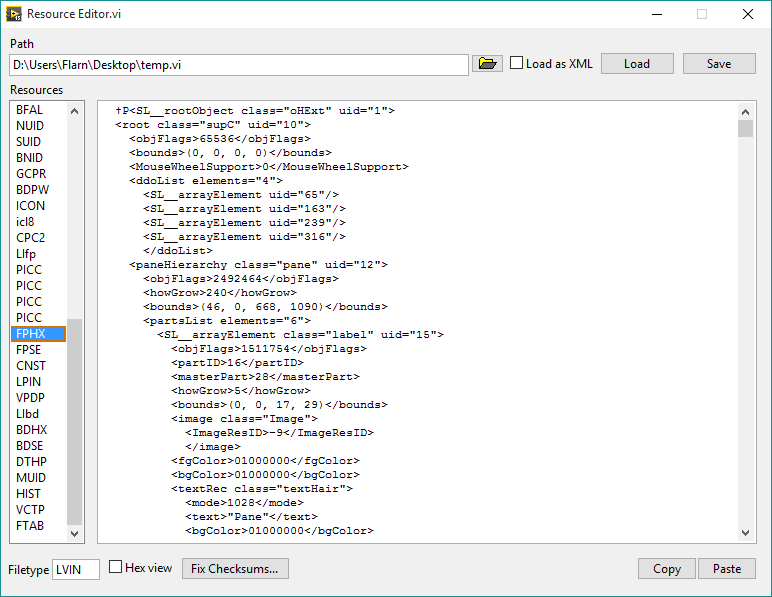
One thing I've always wanted (and have asked about here before) was a way to edit the data inside VI files at a low level. Well I finally figured that out. I have here a tool that will let you open a VI, look at the individual blocks of data stored within, and make changes. Plus, with the power of private methods and internal settings, it can also convert VI's to a format where the front panel and block diagram are XML-based, so you can easily edit the raw representations of objects. Here you go. Run "Resource Editor.vi", select a VI (make sure you make a backup first if you care about it), and click Load to load its resources. Click "Load as XML" if you want to edit the front panel and diagram as XML. If you've edited the block diagram at all, make sure to click Fix VI Checksums. Then just click Save once you've made the changes you want. EDIT: Second version is posted; this one should work in LabVIEW 2014, and fixes some bugs. I also added copy/paste buttons for the front panel and block diagram resources, since LabVIEW's built-in copy/paste function didn't seem to work for some reason. Note that if you edit the front panel or block diagram in the VI without using copy/paste (and the size is different), you need to update the size (first 4 bytes) as well. You can do this by clicking Copy and then Paste. Now this may not be too useful for you, considering it's not something you should use in production code or anything you don't want to break. (I say that a lot in my posts, don't I?) But if you're curious about how VI's work internally, it's perfect. This requires OpenG. Also, special thanks goes out to Thomas Zeugner for making VI Explorer. You know, that tool for cracking VI passwords. Turns out he figured out how the VI checksum (in the BDPW block) is calculated, which helped me greatly. Oh, one more thing, I do plan on improving it. I was just excited to share what I had. So keep in mind there may be bugs. Latest version: The latest version is posted on the tool's home page, here: http://flarn2006.dyndns.org/llvim/ Older versions: Low-Level VI Manipulation rev2.zip Low-Level VI Manipulation.zip
 5 points
 -
So I made a few improvements, first I found that there were relinking issues from trying to load resources normally in the user.lib. The updated one should load from normal locations like the downloads folder (which is where most people are going to try this out from) It looks like you might just not know the right way to make UI's with the event structure. Generally you move the control into the case that is handling it, so that its value is read when you enter. Buttons being latch when released causes them to bounce back, so they are only true for that first time, then go back to false. This means when you enter the event structure it will always have a value of true and you don't need to check it. Polling the timeout case with 0ms isn't necessary. The code does nothing until you press a button or interact with the UI so remove it. I added a case for panel close, so to stop you close the window instead of hitting a button. Prompting for the number of numerics, strings, and paths, had a while loop with 0ms wait which is bad for CPU usage. I replaced it with an event structure. I removed several backwards wires. I added Update While Typing to the string control, so that value changes are registered if you click on the save right after making a change. After a load it picks the first resource to display. Functionally I think it is the same as what you had. Now lets talk about this fix MD5 business you have going on. You prompt to ask how many Numerics, Strings, and Paths are on your connector pane, but you never use this data to calculate your salt. But even if you did you need to be aware that this includes going into other controls. If you have a single cluster with two numerics in it on the connector pane, and a scalar numerc also on the connector pane then you have 3. So this needs to include things like numerics and strings in error controls. A more robust method is to calculate the salt by reversing the equation and guessing what the salt is. I've done this in the past by assuming something like, there will be no more than 20 numerics, strings, or path controls on the connector pane. This could be increased of course. But with a known good VI you have the MD5 output, and the data going into the MD5 you just are missing the salt. An equation with just one missing variable. So if you keep guessing the salt, making the assumption that there will be no more than 20, then it doesn't take too long to go through each possible combination finding the one that makes the equation MD5 = Data + Salt. If you want you can remove the limit of 20 setting it to 255, but it would take a decent amount of time to go through all 255*255*255 possible combinations, where 20*20*20 is more realistic. You also aren't fixing some issues when VIs are part of a library, I believe there are other checksums that need to be updated but don't remember what they were exactly. Oh and was the XNode necessary? Could you just perform the search on the string name "LIBN" instead of taking LIBN then looking up the type as a number? And I know this won't work for all versions of LabVIEW. You know how Ned lets you save in multiple binary modes? That's because older LabVIEW versions used the older binary methods, which might have different named blocks, so BDHX I think is some times BDHA or BDHB. And 2015 is really new, most people aren't going to have it, an older version might have been a better choice. Low-Level VI Manipulation Hooovahh Edit.zip2 points
-
I don't see how it helps. It's just another wire to trail around except it won't sequence execution like all the others do. If my subVI is truly asynchronous I can take that sub VI and put it anywhere. I can dynamically launch it. I can run it on a another computer. I just don't wire between loops - it's clutter that requires decoding. Its not to do with visualisation. It is encapsulation and breaking dependencies. I create self contained autonomous "nodes" that can be tested in isolation. Can be transplanted from project to project, Can be distributed as a single entity and can be worked on without the rest of the application. It just has the side effect that it really cleans up the diagram and makes it look much simpler than it really is. My mind is a dark and foreboding place I will describe how I see software and it may cast light on why I like LabVIEW over the others and how I currently use the VI hierarchy window and design software. Probably more than your asking for but it may help In a nutshell, I see dead people 3D systems. I don't see these systems as lines of code or flow diagrams or other abstract sensations at that level. I see them like in the hierarchy window but in 3D. More like Firefox 3D view but infinitely big. Where there are icons, I see real devices that I've used or know about. Where there are lines, I see TCPIP, Serial, broadband and satellite comms. I see mains cables, probes and sensors. I can also see the layers of that system like the layers in the Firefox 3D view, I can see cabinets full of devices and devices full of boards and boards full of software and a sometimes a rough BOM. You know when the girl in Jurassic Park turns security back on and locks the doors with the computer? That's a poor mans version of how I see systems in my head and I can envision them from scratch, from specs or discussions with a customer. At least one of those devices is usually a programmable device and that's where LabVIEW comes in. I can zoom around and in and out of that 3D hierarchy too. I can go to a particular device and inspect it. I can also switch views of that device. I can see it's UI menus and DIP switch settings. I can flip a brain-bit and view it as the wiring diagrams or as a high level schematic of subystems. I can see the exploded view of the accessories and attach them to the fascia to figure out wire routing. My thoughts are very visual and I can view it in many ways. This is also how I view the software. I see VI icons that represent the devices and the databases and all the things in the real world. I can move them around, change their menus and their dip switches-except they aren't menus or dip switches. They are configuration files and VI front panels. I flip my brain-bit to view the software wiring [vi diagram] and click on "Create SubVI" as I transition the subVI to a subsytem and the current VI to a high level schematic. Moving from the real world to LabVIEW is seamless to me. With other Languages I have to build those sub VIs and diagrams in my head and keep them there or reload them from a document/source file. LabVIEW lets me put them directly into code and leaves me free to think about the system not the memory location/pointers or other mechanics of the programming language. It gets the job done rather than being the job. So those new wires don't have a use for me. They are in the wrong "view". I always try to simplify, encapsulate and decouple the wiring diagrams in my code and part of that is reducing wire counts and breaking flow where appropriate.1 point
-
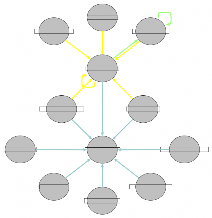
All of that code was just to dump out some sort of Queue Structure into a VI so we could see where the Queues are sending Information to / from in a Map Diagram. The Top level structure of test, test_A, test_B is just randomness (except I ensured there was only one De-Q per Queue). I am just trying to illustrate that part of what a "Channel Wire" is trying to accomplish is indicate to the developer where asynchronous data is accessed / flowing (I am not good with terminologies). A different way of relaying this information is in a hierarchy / map file / class hierarchy diagram, which in my opinion is easier to read. Here is the same rough VI I posted but run on an actual project which includes VIs which are dynamically called (and therefore may not be represented by a "Channel Wire" ??). I have anonymised the vi Names hence the blank boxes.
1 point
-
We address this via the Cloneable DQMH Module. It already comes with clone management and at run time the N number of instances to launch can be selected. We have an example of this in the shipping example. The DUT is a cloneable module. When a DQMH module is created, the tester comes with a button that shows the block diagram of the DQMH Module Main. If the DQMH module is cloneable, then it will show the block diagram for all instances if the ring is set to "All" or it shows the block diagram for the requested instance. This feature was not included in the shipping example, but you can see it in a project created via the DQMH Project template or by adding a DQMH module to your project. In our experience, junior developers get around via the DQMH API Tester to know what is running or pressing the "Show block diagram" button on the tester to see what is going on in the DQMH Main. Most of the time they do not need to go that deep and having a simple API with simple API calls: Start, Show Panel, Hide Panel, Stop, etc means they can do simple VIs that just call a chain of these calls. If they need to debug, they just need to run the tester and use it as a sniffer.1 point
-
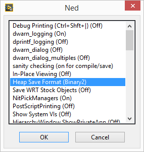
Warning: This shouldn't come as a surprise given the title of the thread (as well as who's posting it) but this is NOT officially supported by NI. Don't use this for anything you don't want to break! I ran a VI that recursively opened every VI in the LabVIEW installation directory and scanned it for Call Library nodes, then saved anything it found to a spreadsheet. And guess what it found in the palette API? Functions that open and save "resource" files, which happen to be the way VI files are internally stored, as well as some other LabVIEW files. It lets you manipulate the internal resources as an array of clusters. Now in case you didn't already know, the front panel and block diagram are stored as binary resources (known as "heaps") in this file, and these functions can't parse that format. So it's not too useful, right? Wrong. Does this dialog look familiar to anyone? That's the hidden internal settings dialog, known for some reason as Ned. To access it, add LVdebugKeys=True to your LabVIEW.ini file and restart LabVIEW if it's already running. Now hold Control+Shift and press D, N. You have to press the keys relatively quickly for it to work. (You can press D, H instead to open Heap Peek, which lets you view the internal representation of objects, as well as their exact location in memory--think about how the latter might be useful!) Now do you see that option I have selected? "Heap Save Format (Binary2)". Click that a few times, and you'll see one of the options is XML. Yep, it turns out LabVIEW has a hidden XML-based VI format. It even opens just fine with the heap save format set to the default. Keep in mind only the heaps are saved in this format; the rest of the file is still binary. But that format can be parsed by those library functions I found. Unfortunately, it seems the block diagram has some sort of checksum and the VI won't load if that's wrong. I know this because after making a simple change to the XML (changing the block diagram's background color) it didn't load, and there was a a 16-byte section in the file that was changed with seemingly-random data. I suspect that this is MD5, considering that seems to be the standard LabVIEW uses, but I tried calculating the MD5 hash of certain parts of the file and it didn't seem to match. Here's two VI's that you can use to turn resource files (like VI files) into resource cluster arrays, and vice versa. Load Resource File.vi Save Resource File.vi And here's a VI that will automatically set the heap save format to XML (using the private method "Application.Call Internal Command"), save a VI (from a refnum), and then put the heap save format back to what it was before. So it basically just saves a VI in the XML format. Save VI with XML Heaps.vi
1 point
-
Manudelavega notes, "...for those of us who have been developing in LabVIEW for years, a wire always controls data flow and execution. This is a golden rule that suddenly doesn't apply anymore, and that's quite disturbing I find." Others have expressed similar concerns in different ways. But: ​That ship sailed circa 1987 when global variables first became a thing. (A few of us were using uninitialized shift registers even before that.) Dataflow is central to the LabVIEW way of doing things, but purity was sacrificed on the altar of power and functionality at that time. The real question is whether there's a use case for this particular innovation, and whether this provides a more sensible and LabVIEW-ish way of representing what's going on. I suspect that if you've done much with queues and suchlike to take advantage of LabVIEW's awesome parallelism capabilities, you'd probably feel it does. I have, and do.1 point
-
disclaimer for anyone who doesn't know me: despite the giant bright blue "NI" next to my name I am not in any way affiliated with R&D so don't take anything I say as a fact about the product. The story I've heard is that they're asynchronous dataflow, similar as I understand it to http://noflojs.org/ This makes sense to me, based on the wiki: So to me it sounds like the big thing that makes something dataflow is that you can explicitly visualize the routing and movement of data which is exactly the intent of these wires (as I understand it) Something else I agree with, but isn't so far as I can tell in the explicit definition, is that an important part of dataflow's simplicity advantage is that data isn't shared. You see how it flows between items but you don't usually share it. When you do (as with DVRs or FGVs), you 'break' dataflow or at least break a key value it provides. Note that this is different from a queue, user event, or the new wires. In all these cases a given section of code explicitly sends information to another section of code without retaining access to that data. The data is sent but not shared. But what if we had started 15 years ago (or whenever) with just these channel wires and queues had never been implemented as a separate concept? What if core 1 taught these wires? I don't really think it would be a problem for anyone experienced and it would reduce confusion for new developers (whats a sv? notifier? occurence? user event? queue? single element queue? rt fifo? who cares?). I personally have zero plans to use these wires in anything I work on, but I do think that if we had created them first there would probably be no need to have added many of the others. I'm curious what this looks like in your mind. Is it a more granular version of this (https://decibel.ni.com/content/docs/DOC-23262) or something else entirely? Something that I'm not a big fan of is the giant fanout of queue wires that occur in many applications. It seems like the async wires would help with this as you can draw the wires between the subVIs which are actually communicating (A->B) rather than the current situation (init->A; init->B). Also, I noticed your comment about shoving queues inside of subVIs and getting rid of the wires entirely. I've seen this many times before and never really understood it, but it seems related to how you want to visualize this stuff, so I'm curious how that concept ("vanishing wires") fits into your communication map concept.1 point
-
I think you maybe missing a trick here. (and probably over thinking the mechanics). Queues, DVRS and all that sort of thing are for moving data around. You don't want to be doing that at all unless it is really,really necessary - and it isn't. You have a local DB. If it's in memory you can lose it easily so by val, ref, DVR or globals is kind of irrelevant to that requirement.. If its on disk you can lose it, but it is much much less likely. Especially if you have an ACID compliant database. You know that. That's why you have two databases. You have a remote DB. That's good - all the managers can run their reports . You have a local DB - that's even better. That's your DB to abuse and misuse . So treat your local DB like memory storage. It's only performance that is the issue and its not much of one unless you are streaming, It's not as if it costs $ per write. Design your tables and as soon as you have a measurement, stick it in the local DB-don't store any measurement data in memory. Even configuration can be queried from the DB just before you need it. If the operator or anyone wants to see pretty pictures and numbers on screen. Query the DB and show them. It will have the effect of completely separating the acquisition/test system from the user interface. If you take a look at the SQLite API for LabVIEW it has an example of data logging (picture on the right with the sine wave). It saves data to a DB while at the same time showing the operator a plot of the data. It does it pretty fast, (about every 30ms) but you wouldn't need that performance. You'd just need more complex DB relationships and tables but the idea is the same. Data is acquired straight to the DB and never sits in arrays or shift registers or queues or DVRS or anything else.The UI queries the DB to show plot data about every 100 ms to prove it's actually doing something Use any architecture you like for your configuring of devices, keeping the operator amused and running housekeeping, it doesn't matter for the data storage. But you've already decided how your going to do that - #4, right?1 point
-
There are two things I'd like to say about this thread. 1. It underscores for me how often CLA-level "in-house" projects are undertaken that run more or less in parallel to other such projects. In some ways this is a very good thing as it allows for diversity in approach and implementation but also a robust degree of competition that, hopefully, increases the overall qualitym usability, scalability and extensibility of the various offerings. We have some very brilliant and creative people in this community! But there is also a downside to this diversity and that involves confustion to the populations end-customers who look for well done implementations of whatever "needs to be used" so that their requirements are met. I mentioned the idea of conmsidering some form of "steering committee" to at least somewhat coordinate all of these efforts so that there isn't just a glut of competing toolkits overwhelming the Tools Network. 2. The second point concerns this following specific exchange (just above): Quote So if I needed a CAN actor for doing CAN communication, I would make that actor and call it in parallel with all the other actors. They all started at the same time, and all stopped at the same time. No actor ever shutdown, without sending a message to shutdown the other actors. We wanted to make it possible to restart a module without having to restart the entire application. I continue to work closely with Delacor and greatly appreciate this specific feature in the DQMH. My project calls other stand alone 3rd party software that can be separately shut down by an end-user and we need to be able to restart that separate EXE asynchronously when that happens, however it did happen. To be clear, it is impossible to prevent or trap that end-user action (to preclude that 3rd party EXE from being shut down) so we have to be able to detect when that has occurred and then restart the previously shut down 3rd party application autonomously, without further input or interference from the end-user. The DQMH supports this essential functionality. Other approaches might well be more appropriate in other specific situations (as in “Your mileage may vary…â€) but overall I think this is an extremely well implemented Template. ​1 point