

ShaunR
-
Posts
4,852 -
Joined
-
Days Won
292
Content Type
Profiles
Forums
Downloads
Gallery
Posts posted by ShaunR
-
-
QUOTE (Warren @ May 29 2009, 09:41 PM)
I had hoped to set up this little experiment to learn more about Serial I/O to use in a future project - However I have had no end of difficulty just starting with this. I have a small circuit with 4 LEDs connected in parallel to (2,3,4,5) pins on the port. (I have 470 Ohm resistors in series with each of these) I have tied (11, 12) to ground. I have attempted to use labview to send some form of signal to the LEDs without success. I used both the serial VISA and out port. I have also reviewed the examples (Basics serial read write) but I think I have forgotten somthing, or I am doing somthing fundamentally wrong. I have also read through many online sites about the fundamentals of the Serial Port - but I must be missing somthing.Any help would be greatly appreciated. - Let me know if there are any details i neglected to mention.
- Warren.
Ok. Couple of points.
1. Most parallel ports nowadays have internal pull-up resistors (4K7). Whilst this makes input a lot safer/easier, it means that drive capability is severely restricted. This might be limiting your current to about 1mA (a DVM will tell you if this is the case or not).
2. To use the parallel port as digital IO in Labview, you need to make sure it is set ti "Standard" in the bios (Not SPP,ECP etc).
3. There is a parallel pot example of using it as a digital IO in the examples directory (Port IO) and I would suggest using this (as it is a direct port write) rather than VISA to get it going.
-
-
I don't really know what problem its trying to overcome, but all the methods stated work for me
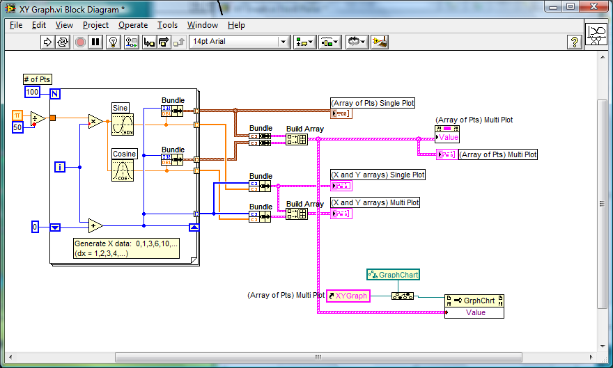
You might also look at the "Many To One" queue example if you are looking to combine multiple single plots from other VIs..
-
QUOTE (Vladimir Drzik @ May 25 2009, 07:54 AM)
Guys,Thanks for the answers. Well, it also seems unlogical for me for NI to include LV editor in the runtime. But... the calculator step in Vision Builder is actually THE LV editor. It even uses the settings from LabVIEW.ini of the current LV development version. And it works also without development version installed (though I'm not sure which INI file it uses then).
Anyway, it wouldn't be a big problem for me if the development version was required to use the editor inside my application.
I'll also contact NI and let you know if I find out any new information.
Vladimir
I've just been looking again at the VB. In fact, you seem to be right (I haven't used the VB for years so thought I would refresh my memory). The "Calculator" does seem to have a Labview editor built in with an extremely reduced palette. I've no idea what they are doing since you don't have to have Labview installed to use it (but you do to Export). I'm guessing that they've cut out the LV editor core and implanted it in the exe. Let us know the feedback from NI.
-
QUOTE (Black Pearl @ May 25 2009, 08:40 AM)
As far is I read the other posts, we all use events to pass the error data. Other ways of doing it?Felix
Thats probably because everyone here uses the same topology. (centralised error handling). I use local error handling, since a lots different stuff has to happen if there is an error (not just tell the user) and that would make a centralised error handler a bit of a pig. The only common denominator is that I have to put a dialogue on screen and halt other processes execution ("Launch Error Dialogue.vi") while the operator decides what to do. In the meantime the process that threw the error tries to recover to a safe/stable state. The "Launch Error Dialogue" loads and runs (yup, you guessed it - the "Error Dialogue.vi) which logs to a file and filters the error to provide different options to the user (if required). It can be called from anywhere in the code and can remain on-screen, not show at all (i.e just log) or time out after n seconds (depending on the error level). It also does other things like set off a siren, change traffic light indicators etc. Nice and simple and just plonk it in your error case of the state machine.
One thing that hasn't been discussed so far is error levels.
In my system(s), I have severity/priority levels for errors (Information, System, Critical, Recoverable, Process and Maintenance). What do other people do to prioritise errors (if anything)?
-
-
-
QUOTE (n00bzor @ May 24 2009, 08:40 AM)
I used a 0.12k and that didn't seem to do anything. I'm going to try it again for a larger value.Also, what do you mean by "crowbar"?
0.12 is still far too low. It equates to about 41mA (V=IR). Try a 1K5. Then measure the voltage across the digital output to ground. If its at 5V (or very close) then that isn't the problem.
Many output sources (digital/analogue outputs, power supplies etc) have a system of protecting the circuitry from short circuits (a fuse for example). The term "crowbar" in protection circuits is analogous to "being hit over the head with a crowbar" i.e instantly halting the cause of the problem to protect the curcuitry.
-
According to the specs. The U6009 is digital rated at 5mA and according to the current transfer characteristic of the 4N25, it should work down to about 0.5 mA (although you wouldn't get much out of it). It may be that the digital output is detecting the LED as a short (don't know if it has a crowbar or not...but might). Try putting a 1K5 in the digital line to fix the current to about 3.3 mA and see if that works.
-
QUOTE (Vladimir Drzik @ May 21 2009, 04:25 PM)
Shaun,Subpanels allow you to embed a front panel. I need to embed the LV editor. Or am I missing something?
Vladimir
Sorry. I misunderstood.
The only thing I think your missing is that VBuilde/VAssistant doesn't actually have the Labview environment embedded. It is a pictorial representation of the functional blocks with its own editors ,and, when you execute the code, it interfaces directly the the NI vision dlls. The only time that Labview is used is when you want to create the vis. Then Labview is launched and the vi's are generated (probably using scripting).
-
QUOTE (Gary Rubin @ May 23 2009, 12:46 AM)
As far as I can tell, and someone can correct me if they've gotten this to work, is that the Gate applies for input counters, the Pause is the equivalent for output counters (i.e. pulse generation).Indeed. But you can use can set the output to trigger off of an input and gate that input (just wire it to the other output). I think the "Pause" just pauses the generation from the software making it difficult to synchronize continuous pulse trains. Whereas Gating is done at the hardware level.
-
Best advice I can give.
When you find a good AE, get his/her direct line number and put it in your contacts list.
I've been using the same guy for the last 3 years and you don't have to spend 15 mins going through all the secretarial rubbish to get to talk to someone

QUOTE (Gary Rubin @ May 22 2009, 03:27 PM)
I think what you are after is the Counter Gate. (CTR n GATE) It enables you to Start/Stop/Mask counters (if configured). You have to sacrifice a PFI, but if I remember correctly, the 660X series have loads of them anyway.
-
QUOTE (angel_22 @ May 22 2009, 02:51 AM)
QUOTE (jcarmody @ May 22 2009, 07:56 PM)
This reminds me of my Senior year in High School when my Electronics lab partner told me to "hurry up and fix it, I want to get this done."
lol. He was obviously a manager in the making
-
1. Is the PIC on an evaluation board or have you built the board yourself? (I hope its the former!!!!)
2. Has your PIC got software in it? (You have to program a PIC to use its USART and there are plenty of examples of this on the net)
3. If you are using an evaluation board, have you successfully downloaded a program/example with the tools that came with the board.?
If you are at No.3 then (and only then) you can start thinking about Labview. You will then be able to use VISA to open the Com port and write/read the command strings/data using the settings from the example and you should be good to go.
-
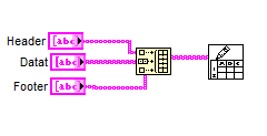
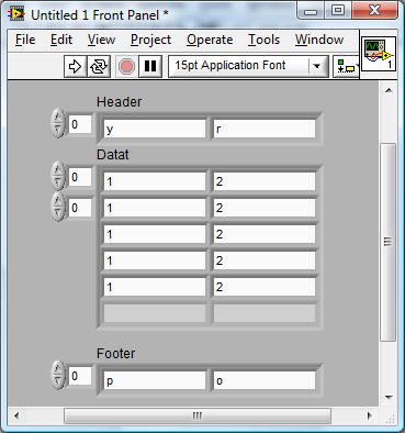
You can also write headers and footers in one hit.


-
QUOTE (rahul @ May 21 2009, 05:56 AM)
I am working on a multiple camera project.The cameras are connected to the IEEE 1394 (firewire) interface.
Driver---NI IMAQdx IIDC
I am facing a problem with the detection of cameras after an improper shutdown (like restarting ,hard booting etc..)
Then i have to replug the cameras to get it detected..
They are not even detected in the Device Manager.
Why is it so and how to solve it?
Is it a problem withg the WINDOWS boot procdure && if it is .. how to detect the cameras without replugging it?
PLS reply (URGENT)
We had a lot of problems with firewire (including what you are seeing as well as cards not allowing windows to boot and having to use a hack to get more than 100Mb/s which only worked sometimes between boots). So much so that we now use GigE (much better) It's only some windows installations that are problematic and (I'm afraid) we did not find any solutions.
-
I've got one of these that I wrote before we had the spreadsheet vi's.
You don't need that many. Just pre-process with a for loop (to give the page and you can check the dimensions to bypass) and use the build array just before you save to to append/prepend a header and footer (your description can be part of the header or footer or you can have a separate one). Then just wrap that as a poly vi for your different types.
You can also do things like checking that the file exists and only writing the header if its a new one and appending instead of overwriting so you can use it as a logger (don't forget an override switch though
 .
.I actually prefer to save different "pages" to separate files as you can load each one up as a separate sheet and it makes graphing and things easier.
-
Subpanels. Example in the usual place.
-
QUOTE (SLearner85 @ May 20 2009, 05:52 AM)
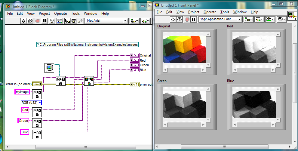
Hi. I am doing my school project which required the assistance of the IMAQ Vision. Can you show me some example on IMAQ Vision using LabView.Thanks a lot.
No...... But your hard disk can. There is an "examples" directory and if you have vision installed there will be examples in there.
-
-
QUOTE (angel_22 @ May 19 2009, 02:46 PM)
where are you???i want the method to bigun the system with logon widow
please reply
thanks
lol.Some of us have to work for a living!
As Asbo said. there's an example.
Your UI is comming along nicely. You obviously have an artistic flair which I severely lack.
Is this software actually going to control anything? Or is it a proof of concept?
-
QUOTE (Gavin Burnell @ May 19 2009, 04:57 PM)
I use this sort of architechture for working with my instruments - I have a very generic "instrument" class that provides vi's that wrap VISA functions but with additional debugging code that I can turn on and off, a layer of classes that define APIs for different type of instruments - e.g. source meters, temperature controllers, lockins, magnet powersupplies and then a layer of classes that implement the interface for specific instruments (or even combinations of instruments). This is sort of reinventing the wheel in that it duplicates IVI drivers, but (a) I know exactly what commands are being sent to the instrument and (b) I get to design the interface layer.This is exactly what I was trying (rather failing) to describe on the "Exterfaces" thread.
-
You could do all that, but it might be easier to use use the "Overlay" functions in the "Vision Utilities" library.
-
QUOTE (keat007 @ May 18 2009, 01:14 AM)
As my Toothpic is on its way
I decided to look at the software for programming it. You can download a free toolset but I think what will be of more interest to you is that they have existing firmware for acquisition. I think if your looking to get up and running quickly and not too bothered if you use Labview or not, then it might be worth reading this. Looks like the server is in the bluetooth device (ike a webserver) so data can be viewed on anything from a PC to a mobile phone.http://www.flexipanel.com/Docs/DARC-II%20DS382.pdf' rel='nofollow' target="_blank">DARC II
Oh. they ship to Singapore from that link I gave you


Hopper Filling/Emptying vi
in LabVIEW General
Posted
This would be a good starting point.
LabVIEW 8.6\examples\apps\tankmntr.llb