

ShaunR
-
Posts
4,942 -
Joined
-
Days Won
308
Content Type
Profiles
Forums
Downloads
Gallery
Posts posted by ShaunR
-
-
It took me longer than expected to reload Windows 7 64-bit RTM.
I ended up doing the following:
- Installed LabVIEW 64 by itself (since it isn't on the DVDs afaict)
- Ran normal DVD installer and picked all the toolkits for which I have licenses. The installer seemed to recognize the existing LabVIEW 64 and automatically activated the appropriate entries for it along with LabVIEW 32.
- Reboot
- Ran the NI-RIO 3.2.1 installer from NI.com
- Reboot
- Opened my project and went to the CRIO FPGA node
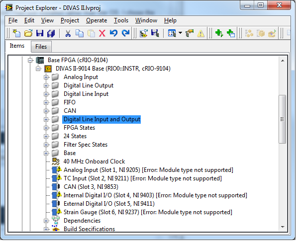
I'm further along than before since Realtime nodes are now recognized. But LabVIEW still thinks I don't have all my files. Look at the screenshot:
I tried rerunning NI-RIO 3.2.1 and picking all the options. It resulted in a no-op and didn't see the need to install any files.
A google search didn't give me any useful hits. Any suggestions?
Progress

The compact RIO (cRIO) is a separate installation on the DD DVD.I didn't install it since I don't use cRIO (far too expensive) so cannot verify the installation, but looking at my installation I have NI-RIO 3.2.0 and NI-RIO 3.2.0 real time driver installed since vision is dependent on them (quite why I have no idea). I would suggest going back to the DD DVD and installing the Reconfigurable IO section and all its dependents and see if that works.
One thought. It you are targeting cRio, it probably isn't 64bit so compiling to 64bit isn't really an option. It might be that the target is only possible on the 32 bit version. Whilst NI do supply FPGA cards for PC's, they probably can be targeted (and therfore the need for the NI-RIO driver core), hence the "Module Not Supported" lines in your screenshot.
-
I'm sorry to All,
I forgot to wrote the error code that application return back. So, it become more difficult for yuo to help me.
This is the error that return from my application:
Error -1073807253 occurred at VISA Read in COM_Port_Handler.vi->Serial_CORE_Engine.vi->Main.vi
Possible reason(s):
VISA: (Hex 0xBFFF006B) A framing error occurred during transfer.
I opened a ticket with NI and an engineer answered me that this happen becouse there are noise on the line and I loose some information on the package. But, I don't understand why this happen for normal RS232 pc port and don't happen with FTDI USB converter. I use only one line and one software.
For who want to try to read the ticket, this is the address: http://forums.ni.com...message.id=2065
but it is in italian.
For the moment I resolved the problem cleaning it.
P.S. Sorry to all for my bad eanglish.
This usually occurs with an incorrect baud rate or a baud rate that is not one of the "standard" ones.
-
This is correct, but i think that creating this behavior is simple. You could use events to create this situation - for instance, use an event-driven loop to wait upon a variable change event and not allow any other code execution until the event takes place (say, by using a notifier to notify local VIs!).
Ooooh. Its all got very complicated, very quicky. Now we have variables, events AND notifiers

Take your proposed topology. Replace the variable with a queue. Don't bother with events since the queue will wait and you have what I said a few posts ago about a 1 element lossy queue!
The only reason you can't use a single notifier is that you have to already be waiting when it fires or (if you use the history version) you have to clear it before you wait.
The DSC Module allows one to create shared variable value change events that one can wire into the dynamic event terminal of an event structure.
The DSC Module also allows one to create shared variables programmatically at run-time. (I see jgcode just mentioned this.) Currently this feature only supports basic shared variable types, unfortunately.
In our code we use shared variable events a lot and they work great. In practice we haven't needed to create SVs from scratch at run-time yet. We have done something similar by programmatically copying existing shared variable libraries (with new SV names) and then deploying the copies, which is a useful way to work with multiple instances of a component.
Shared variables have come a long way from their original instantiation and I think networked shared variables are a pretty reasonable implementation of a publish-subscribe paradigm. They can be pretty easy to implement. (Don't get me wrong, there are some things I still want to change, but we find them quite useful.) I recommend taking a fresh look at them.
Paul
Not every one has (or can afford) the DSC module. Queues, notifiers and network shared variables all come as standard. Coding around it isn't difficult with the built in tools. Its just bloody annoying when a single notifer with a history that gets checked off everytime it executes would halve the code complexity. In fact, it shouldn't really be called a "notifier with history", perhaps a better name would be "notifier that gets round the other notifier bug"....lol.
-
I think that network shared variables do everything that you've requested.
I don't believe they intrinsically suspend execution until an update is received. They also have huge caveates (e.g cannot be dynamically created at run-time). Its a bit of a sledgehammer to crack a nut IMHO.
-
Hi, I have used a tresholding method to my original image and I get a black and white image. I need to transform it to a binary image. How to do it? It is still grayscale in output. Thanks.
Instead of replacing threshold values with 255 (to get your black and white) replace with 1. Your picture control will look all black. If you want to see the results in the picture control, right click on it and select Palette>binary. You will then have a red and black image. Either your black and white or red and white images (binary) will work with mask functions as effectively they operate on zero and non zero for binary operations.
-
Hit Prt-Scr. Doesn't get much easier than that.

And press "Alt" to get just the active window.
-
Hi!
I've tried to search the Google and the dark side, but I didn't find anything useful. I'm asking here first because there's usually more knowledge around.
Here's the scenario:
I'm downloading all files in a directory from a FTP server in LabVIEW 8.6.1 using the NI Internet Toolkit and the FTP VIs .
If a local file exists, I'd like it to be overwritten. I'm using 'NI_InternetTK_FTP_VIs.lvlib:FTP Retrieve Multiple.vi' to do the job. It does the job just fine if the files do not exist on the local computer. But when files exist, it returns errror code 8 with message 'EOF' for the offending files in the file error array. The LabVIEW help doesn't give any clue in the VI documentation, as usual.
Now I've pinpointed the problem in 'NI_InternetTK_Common_VIs.lvlib:TCP Read Stream.vi' and 'NI_InternetTK_Common_VIs.lvlib:OpnCrtRep File.vi': The input parameters to latter indicate an operation to create or replace a file in read-only mode. See the problem already? Inside 'OpnCrtRep File.vi' the operation parameter is happily ignored when actually trying to open the file, but read-only mode is set. Next, when creating or replacing a file, the VI attempts to set the file size to 0. Which gives the error code 8. Nice.

A question: do I have to roll my own solution? To my eyes either the FTP VI is broken or then I'm just being stupid. The documentation says nothing about this and as I understand from the comments inside the code it should overwrite the file.
Anyways, time to go to the big blue room to calm down...
Cheers,
Jarimatti
I would defensively code a check to see if the file exists, force its attribute to be writable and delete it before trying to save (I actually do this anyway with overwriting files and have done for years). Then phone NI to see what they say. There may be a reason for it.
-
 1
1
-
-
On the hour every hour all hell broke loose.

Sounds like my workplace
-
Option 1: Create a queue, a notifier and a rendezvous. Sender Loop enqueues into the queue. All the receiver loops wait at the rendezvous. Receiver Loop Alpha is special. It dequeues from the queue and sends to the notifier. All the rest of the Receiver Loops wait on the notifier. Every receiver loop does its thing and then goes back around to waiting on the rendezvous.
Option 2: Create N + 1 queues, where N is the number of receivers you want. Sender enqueues into Queue Alpha. Receiver Loop Alpha dequeues from Queue Alpha and then enqueues into ALL of the other queues. The other receiver loops dequeue from their respective queues.
Option 1 gives you synchronous processing of the messages (all receivers finish with the first message before any receiver starts on the second message). Option 2 gives you asynchronous processing (every loop gets through its messages as fast as it can without regard to how far the other loops have gotten in their list of messages).
I'd prefer a "Wait on notifier history" that only executed the number of elements in the history. LV 2010?
-
Unfortunately, you can't time an animated gif well enough. The animations have too loose a time slice to be reliable, and anytime the UI thread gets tied up, they can hang. Further you have no ability to reset it in LabVIEW -- whenever you launched the VI, that would be the time displayed.
A pendulum swinging is just eye candy. You don't need to synchronise it.KISS.
-
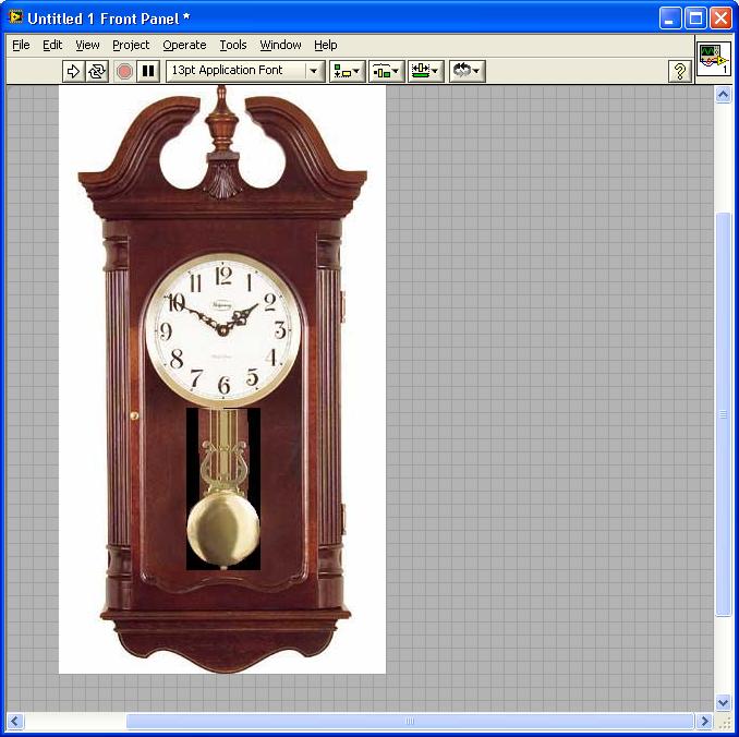
Trying to make a clock interface.
In the image, the Pendulum and clock needles are controls. I try to make the Pendulum move as a real clock, but how to rotate the control. I can move its position from right to left, but doesn't seem like a clock anymore.
So can I rotate the angle of a control? A control doesn't have a property about its own angle.

Animated "Gif" image.
-
I had this problem recently.
My scenario was that the asynchromous consumers could either send a "completed" notifier immediately (no part present) or after some arbitrary amount of time (part has been processed). The sequence engine would wait for all notifications from the subsystems, index a carousel and then send a "Go" notifier to all of them . The problem was that if the subsystems sent it immediately, the chances were that the sequence engine wasn't waiting for the notifier at that moment in time, so on the next round would wait indefinately.
The elegant solution would have been the "Wait on notifiers with history". But this doesn't wait again unless you've cleared the notifier and since you don't know which is the last one in an asynchronous system, you don't know when to clear it. If it executed the number of times there were notifications in the history....it would be perfect! The normal notiifer will only execute when you are actually waiting (if ignoreprevious is true) or again, you need to clear it (if it is false). So that didn't work either since the sequence engine was unlikely to be already waiting if a subsytem returned immediately.
So I ended up with all the subsytems waiting on a notifier to "go" and a separate 1 element lossy queue for each subsystem to send back the completed (basically a notifier with a history of 1). Luckily I have a Queue.vi so it wasn't messy and just meant replacing my Notifier.vis with the queue one.
-
I was referring mostly to the difference between your two test codes. One does an operation inside a loop, the other performs the same operation on a vector. Of course, most of the time you're using a loop, you have no choice in the matter because of the need to iterate.
That said, one example is a phase wrap on a vector. The logic is: if a>180, a = a-360. if a<-180, a=a+360. Because LV's Select does not allow the boolean input to be a vector, my first thought was to use a for loop. Instead, I was able to come up with a more efficient vectorized approach using modulos.
Indeed.
For me it depends on whether I want (or need) to spend a day thinking about an elegent approach for a trivial part of the program or just want the results.
I'm not particularly a purist, so if its neat, easily understood but not the quickest piece of code on the planet, then thats fine.
-
Ok, I get the factor of ~2 speedup from the 5.08 seconds to the 2.887 seconds, but I'm pretty surprised at the last line. I think I would have have expected no difference, as both cores should already be fully committed by virtue of the code loop being parallelized.
And now you see why I avoid for loops whenever possible. The Boolean to 0,1 likely has an allocation associated with it, which is why you don't want to do that in a loop...
Surprised me too
. But maybe optimisations are coming into play.Not sure what you mean by "whenever possible". If you need to "iterate" then I don't really see any other alternatives apart from "while" loops which don't have inherent capablity to dynamically terminate on the array length. Example perhaps?
-
Thanks, but I'm after a little bit more info. It might've been my first post to the forums, but I'm not new to LabView (been programming 5+ yrs).
Some things I heard / read somewhere over the years that caused my questions.
They may be true, they may not...
- Timed loops only execute on a single thread, regardless of how many loops you have (4 timed loops, 1 thread...doesn't make sense to me?).
The thread that anything runs in is not dependent on the loop (LV 9.0and "for" loops excepted) but the "Execution System" that you define. Additionally, the number of loops is irrelevent. Its the vi's that count! The max thread count is 8x5x5 = 200 (8 per execution system x 5 execution systems x 5 priorities). The default is 4 per execution system with 0 for background . So if you look in process explorer you will probably see 21 threads (4x5=20 + 1 for LV itself). Therefore, if you have 4 threads and 12 loops in 1 execution system in 1 vi which is at "Normal" priority,then the LV scheduler will split the 12 loops between the 4 threads (black magic NI secret how this is applied....chime in here LV gurus!). If you want to ensure that a single loop runs in a single thread (not documented but works for me). Then run those loops in their own vi and in diiferent execution systems (I use other1 and other2 a lot) and in asingle vi. If you change the threads per execution, then you will see the threads grow in "Task Manager". Bear in mind, that LVpre-allocates threads, so you will only see the difference when youre-start LV.
One further point. Don't confuse parallelism with multithreading. You can run 2 loops in parallel but LV may only run them in 1 thread and "timeslice" between them.
A usefull utility exists in vi.lib\utility\sysinfo\threadconfig.vi where you can change the thread allocations.
- Timed loops are not compatible to run on AMD processors.
Clarity?
- Don't know. None of the PC's we use have AMD processors, but seems a bit unlikely.
-
Oh, right. I guess the shift register would get in the way... I haven't played with that feature yet (or LV2009, for that matter).
Actually, that got me thinking. I wonder what the performance difference is between your original looped approach from a couple days ago and the unlooped one. And does that change significantly if you multithread the looped one?
Intriguing question. Well.
For loop original 10000 runs = 5080 ms.
No for loop 10000 runs = 2ms
For loop with 10000 run loop normal but code loop // (2cores)) 10000 runs = 2887 ms
For loop with 10000 run loop // (2cores) and code loop // (2cores)) 10000 runs = 2 ms

-
Or better yet, post me a comment in the attached discussion forum so that I can make it what people want it to be
.Don't know where the "attached discussion forum" is, but I've thought for years that "Elapsed Time" should be in ms resolution. It would have been useful then
. -
Ah, I like that one!
Especially if you're using LV9 on a multicore system and can multithread the loop.
Unfortunately you can't because it uses serialised data. I've actually found very few scenarios (so far) where I can use that feature. That maybe due to how I partition my code and the type of implementations.
-
The output of your example just provides a mask that indicated when the data is valid.
I don't think that's his desired output.
Now your just being difficult...lol.
-
Also you can type in 248 on your numpad whilst holding down the alt key. Works in anything (word, excel, labview, notepad).
-
1
-
-
A while loop with nothing will be the fastest. But it will hog your processor (although I've noticed 2009 it only hogs 50% instead of 100%) and it will be hit and miss whether other similar loops get in or not. The next is usually a wait ms with a 0 wait time as it allows context switching so your other loops at least get a look in. Timed loops under windows are better used as a periodic function rather than (in the realtime context) a deterministic function since you are still at the mercy of the windows scheduler. The rule of thumb is. if its time critical......don't use windoze!
-
Ideally I need to find the start and stop of all the gaps. I need separate out and save the chunk of data between the gaps.
George
Using loops isn't necessarily a killer, but I do need to keep processing time to a minimum.
I think a SMA could work, but I think it'll be a little sloppy on finding the edges of the gaps (depending on how many samples I average).
Thanks for keeping the ideas coming. They may not work as is, but usually I get enough of a nudge in the right direction to figure it out.
George
Labview is highly optimised for "for" loops. They are very efficient. Far more so than most other array primitives/operators.
I think that only does half the job. You'd still need to look for 2 consecutive 0's.
Try it.
-
While we're being creative, here's another way to do it. Again, it works for this particular sim data. Not sure it's any more efficient than the diff method though. Curious to see your approach.

Litteraly...you don't need the for loop.
Your comments got me to look closer at my simulated data. I knew my real data would be noisier, but it will also look more like a sine wave than the triangle wave I had. I bumped up the sample frequency and now it looks better. Sorry to say though that the contributed ideas won't work on the new data. I'm back to my original plan of finding peaks and differentiating. By finding the time between peaks in the differentiation I can get the gaps. OK anybody up for round 2?
George
Still works because its only detecting zeros which (in both your examples) only exist in the gaps.
-
Well you can't get much simpler than that.
Ahh. You can. You don't need the for loop either

LabVIEW gives me alot of spare time for LAVA
in LabVIEW General
Posted
I use quad cores and yes 8.6 was a dog (nearly 1 minute to load). I commented on another thread that LV2009 was far quicker (4-5 seconds).