

LAVA 1.0 Content
-
Posts
2,739 -
Joined
-
Last visited
-
Days Won
1
Content Type
Profiles
Forums
Downloads
Gallery
Posts posted by LAVA 1.0 Content
-
-
I have also seen that the RT-FTP engine can be slow (even on PXI based, ethernet connections).
So setting up your own data-service might be the best idea.
Ton
-
QUOTE (Neville D @ Aug 22 2008, 11:46 PM)
QUOTE (Gan Uesli Starling @ Aug 25 2008, 02:31 PM)
Sure, no problem. But JPEGs are horribly fuzzy and my thought was that most folks would rather wait...<plug>
If you want to post LabVIEW code I recommend the Code Capture Tool. This (IMHO) awesome tool grabs the code you need, creates a PNG and adds the path to the OS clipboard
</plug>
On Topic, have you tried reading the tasks in MAX?
This is always a good start.
Ton
-
Thanks guys, VHDCI was the word I needed. I found a set at Farnell that ships 10 for €3,30.
Ton
-
-
QUOTE (jgcode @ Aug 25 2008, 02:08 AM)
I did not do the data-to-variant conversion but nor does NI in their course - so I thought it was ok.But then they penalise for it in the exam - I find that very hypocritical, inconsistent & annoying. :headbang:
So what?
No seriously, you should use the 'Data to variant' (I don't do it every time), in LabVIEW 8.0 there was a bug that mixed up variant data in memory.
Ton
-
QUOTE (giopper @ Aug 24 2008, 04:18 AM)
Maybe this will prevent any resource to close the file.
QUOTE (Raymond Tsang @ Aug 25 2008, 12:12 AM)
At last, I managed to capture a screenshot of the error..Error 6 is a 'Generic File IO'
You should disable any anti-virus, scheduling software, screensaver, energy saver utility. Disconnect the PC from the network.
And sit with the PC while the program crashes. If it happens you should look for any new processes started.
Ton
PS Perfmon can give you the memory usage over time of any process, it is included on every windows PC
-
QUOTE (crelf @ Aug 23 2008, 09:14 AM)
thank you for not confirming my senility.Actually in the old days it was the other way around, negative meant error, positive meant warning.
-10401 meant "DAQ Device not found", one of the most common questions we dealt with as an AE.
Another group of current VIs that return an "error code" which does not indicate an error or warning are the FTP VIs. On successful connection they return 220 which is the FTP status for successful connection.
-
QUOTE (Anders Björk @ Aug 22 2008, 02:12 PM)
Those are M3 if I'm not mistaken, and this is M2
QUOTE (Rio C. @ Aug 22 2008, 06:48 PM)
I found this one at Digikey, part number 787004-3 by Tyco.Molex also has one, part number, 71433-002.Thanks for the info.
Ton
-
An error cluster represents an error if the boolean is True.
In other cases it is considered a Warning, though GPIB functions have some codes that mean 'Successfully applied'
Ton
-
QUOTE (jlokanis @ Aug 22 2008, 01:44 PM)
At the risk of inciting controversy or being redundant to other threads in the past, I am wondering how many people feel that LabVIEW should change its image with regards to the programming language G?...
-John
Remember, NI has to worry about MS (think Netscape). It is a good strategic move to not make it appear like MS is threatened by LV.
Ben
-
And before anyone post something to the effect "talk is cheap, show us the code"

I just delivered an app that had about 100-200 controls and indicators (all DSC fancy graphics) that need to update live.
I used a State Machine (State Diagram Editor, remeber that?) to code up a striaght line init before entering the main loop with the event structure.
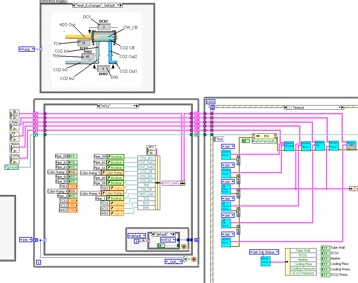
The benifits I got from this was when I developed the other ten screens (that were variations on this theme) I was able to re-use all of the sub-VI's.
Using this approach I was able to transfer support of this application to my customer with very little training (actually none).
Ben
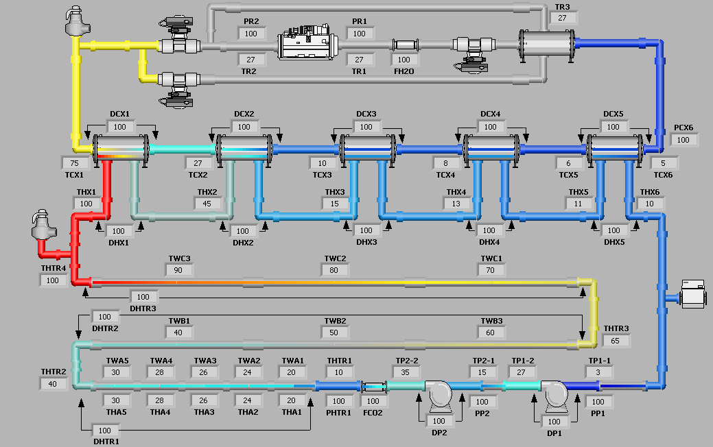
PS This is what the GUI looked like.

-
QUOTE (Michael_Aivaliotis @ Aug 22 2008, 04:08 AM)
To Aristos and the other NI folks arguing that the 3 button dialog VI is fine. All I have to say is, you just don't get it. This type of coding is not acceptable in my books regardless of how much pixie dust you sprinkle over it....
I had never looked at the code in the b-button before today and I have to side with Michael. If all of the prep work had been done using sub-VI's you would at least be able to re-use the sub-VIs in another applcation. And these could have been very handy sub-VI's at that.
Ben
-
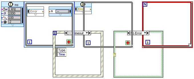
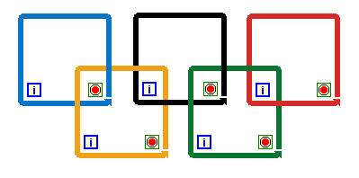
QUOTE (normandinf @ Aug 22 2008, 08:38 AM)
Now... I'll have to refrain form changing loop/frame colors. I didn't know you could do that! I can see how it would make a BD cheerful. I'm just afraid I might look back at those diagrams in a few years and wished I had never known about this feature!Not only can you change the color of the frame, you can also change the color of the background of your entire diagram or the diagram inside any of the structures. This has been used by some developers with more or less success to make a diagram more readable. I agree that you should never change the color of the structure frame as we are used to the colors and it helps us read a diagram more quickly.
To be honest, I changed the colors of the frames in MS Paint, as I also interwove the loops with one another and needed transparency inside the loops, both of which could not be done in LV.
-
QUOTE (jgcode @ Aug 21 2008, 08:15 PM)
There is more information on this topic (how LV FPGA code is converted to run on the FPGA) in this http://zone.ni.com/wv/app/doc/p/id/wv-231' target="_blank">video. The video is a bit older, but the explanation of this process is still the same. The relevant portion start at 14:05 in the video.
-
You can try to reimplement the DSTP protocol (which is not an open standard - no documentation) using low level TCP functions, but I would recommend that you switch over to a solution based completely on TCP for this application, i.e. your server will use TCP to pass the data to the client instead of DSTP.
You may want to look at the STM component and communication reference design on ni.com which provide a good example for implementing low level TCP communication in this type of application.
-
QUOTE (Rashmi @ Aug 22 2008, 05:51 AM)
I am new to this forum as well as LabVIEW. So please help me evenif the question I am posting is simple. I am using Labview 7.1. I have developed a 12 ODE solver using RK 4th order and Fixed step of 1ms and simulation time as 10s. I have used Simulation Module and Formula Node for the same. I have done the offline simulation and it works fine. Now I would like to run the simulation in real time without interfacing any hardware. I mean, the step size which I have given as 1ms, I want the operating system to complete all the calculation(12 ODEs) for one iteration within that period and the task should be deterministic. How can I perform this?Rashimi,
You can run the LV Simulation code directly on a RT controller if you also have the LabVIEW RT module. The local experts recommend moving to LV 8.6 for this, as the performance of the LV Sim code in RT has improved dramatically in the most recent release.
That being said, moving to LabVIEW RT will give you more determinism but it won't improve the performance (speed) of your code significantly compared to an equivalent processor running Windows (your current offline simulation). So moving from a desktop PC to an RT target will not run your simulation any faster (real-time) unless your RT target has a faster processor on it.
-
QUOTE (brianafischer @ Aug 19 2008, 04:27 PM)
One mega-disadvantage compared to PLCs:Programmable logic controllers have the ability to make program modifications online (while running a program). There are limitations of online edits, such that the user variable storage is fixed. However, changes in logic are possible without disrupting a production line. If NI could develop a way to allow for online edits and with the ability to program in a familar language, I could see the real-time/cRIO market become a viable option.
This is one well known shortcoming of the current ladder diagram editor for LabVIEW. Please post any other feedback and suggeations on this tool to the http://forums.ni.com/ni/board/message?board.id=nilabs&thread.id=149' target="_blank">discussion forum setup for this purpose.
-
QUOTE (Raymond Tsang @ Aug 21 2008, 05:46 PM)
Please see here and here for screen shots and here to read what Greg McKaskle had to say abou this topic.
Have fun!
Ben
-
QUOTE (LV_FPGA_SE @ Aug 22 2008, 07:23 AM)
After the NI week, NI seems to run out of work....

-
Hi all,
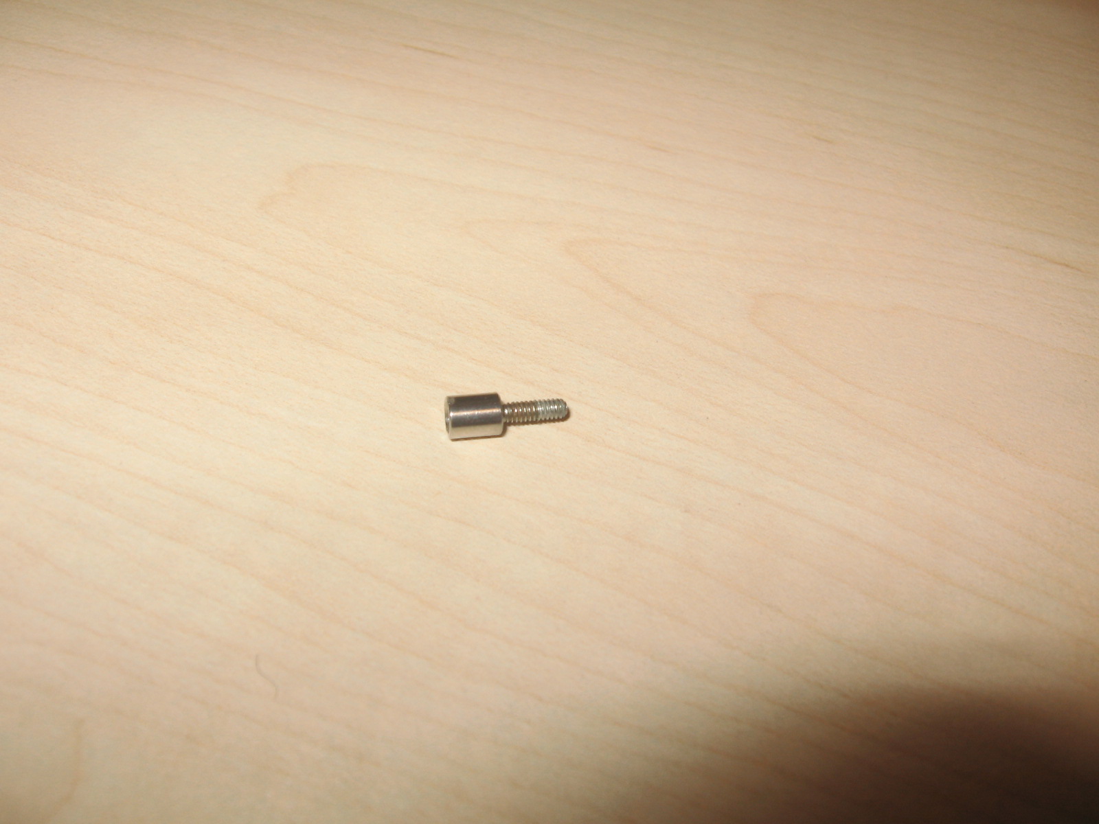
I am missing one of the screw lock connectors on a PCMCIA 6036 cards:
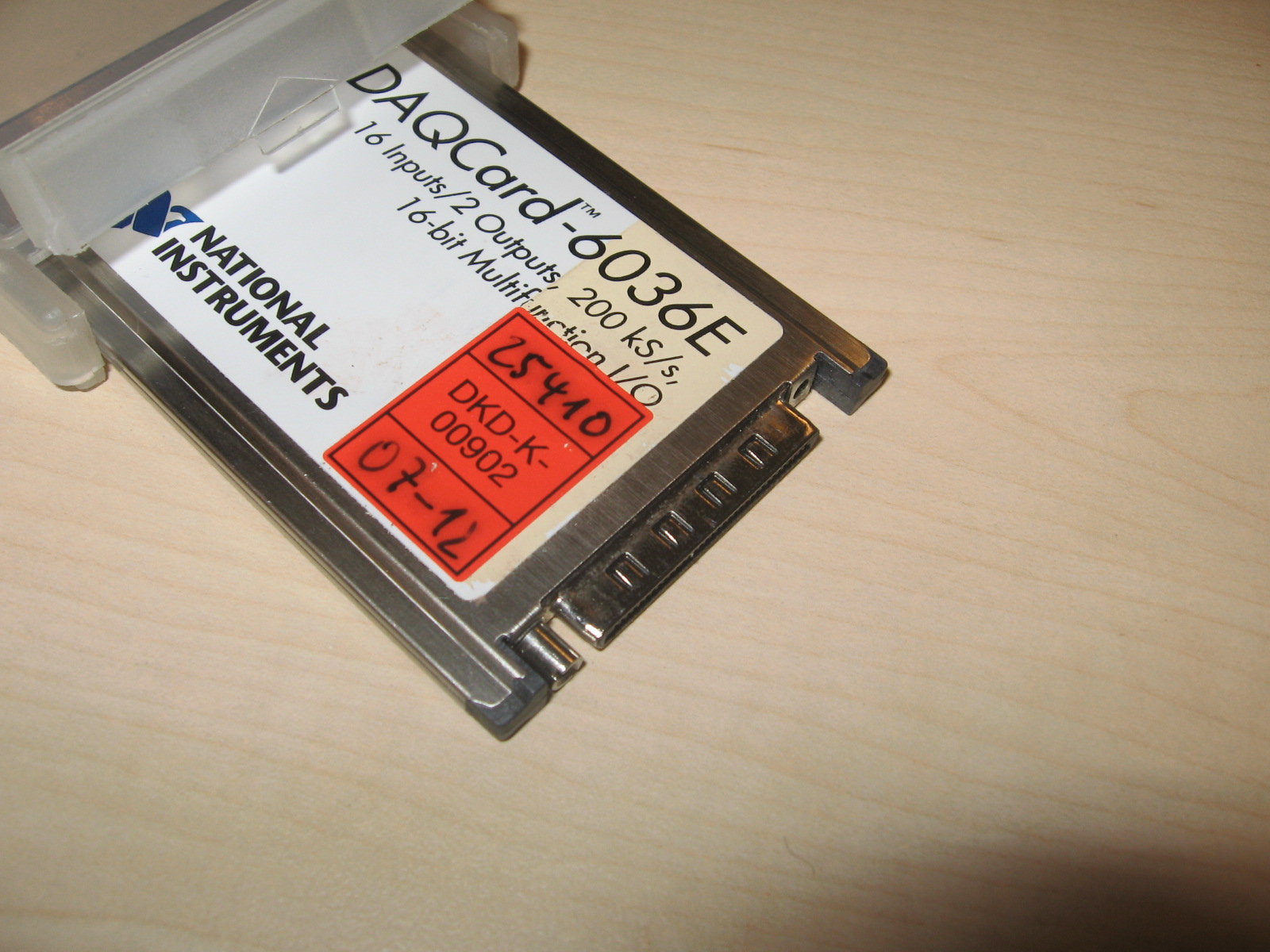
Here's a zoom:

Does anyone know where I can order these? NI didn't have a clue and all my tries on Google resulted in other things.
They can also be found on the M-series HD connectors.
Ton
-
QUOTE (Aristos Queue @ Aug 21 2008, 08:15 PM)
http://lavag.org/old_files/monthly_08_2008/post-3370-1219382545.png' target="_blank">
-
After too much programming last night and watching TV at the same time this vision popped into my head.
-
QUOTE (mross @ Aug 21 2008, 02:14 PM)
I think get it, we have apples and anchors here? FPGA is not compiled code that is optimized to use dataflow. It is just straight up sequences and go to's?In fact the code, more correctly called the bitstream, that is running on the FPGA is more like a digital circuit diagram (think EE, not CS) , than any kind of program. So in order to preserve dataflow when converting a LV diagram to FPGA, extra code/circuitry is added so that the circuit implemented on the FPGA behaves like a LV VI. The most common part of this process is the Enable Chain. The enable chain enforces data flow from one portion of the FPGA code/circuit to the next by setting an enable flag whenever the data output of one piece of code/circuit is valid. The next piece of code/circuit will not perform its action until the input data is valid as stated by the explicit signal from the previous piece of code/circuit.
Due to the mapping of LV code to the FPGA, any wires and data associated wires take up a signficant portion of the limited FPGA circuit real estate "space", so in LV FPGA programming you always optimze your code by minimizing the amount of data on your diagram. Therefore a sequence structure is preferable to data flow if you don't need the data for something else. In addition error clusters don't exist in LV FPGA and are not an option. FPGA programmers don't make errors.
-


OlyVIEW
in LAVA Lounge
Posted
QUOTE (normandinf @ Aug 24 2008, 07:37 PM)
In the diagram you can open the Tools Palette just like on the front panel (View >> Tools Palette) and then select the coloring tool.