Ano Ano
-
Posts
132 -
Joined
-
Last visited
Content Type
Profiles
Forums
Downloads
Gallery
Everything posted by Ano Ano
-

Short out an array according to the elements of another array
Ano Ano replied to Ano Ano's topic in LabVIEW General
Hello, Thank you for your prompt reply. Maite: I want to take the value from the second column of the second array and place it in a second column on the first array at the same location as it was in the second array. Aristos Queue: No this is not a homework. I am too old for school & University:P. It is just that the mind tends to stop when it encounters a problem on simple logic:P I am attaching my code, which seems to do the job (finally). Please have a look and if there is any better way of doing it please suggest it! Thank you in advance. Array Sorting.vi -
Hello, I have the following situation: First array: 1 2 3 4 5 6 7 8 9 10 Second Array: 3 0.01 6 0.08 7 0.03 and I want to create a Third array: 1 2 3 0.01 4 5 6 0.08 7 0.03 8 9 10 Any suggestions on who to do it? Thank you in advance
-
Hello, Has anyone attempted to use omron temperature controllers with Labview? I have a E5CN and I am want to communicate via VISA but I have no idea what to do. Does anyone know?
-
Not sure how this can be done!
-
Hello, Thank you for your replies. jcarmody: I havent mastered yet on how to add images on forum replies! Any suggestion would be most welcomed:) Jon Kokott & asbo: The LED are in the front panel and are turned on by code. When an acquisition event takes place and two conditions are met then a boolean LED turns on; there are 50 LEDs in total this is why I am looking for a For Loop. These conditions may or may not be valid after a while, hence the LEDs may stay on or may switch off. Hence I want to display, in real time, and log the time it stays on and when the LEDs turned on in the first place (as compared to a global timer (when the measurement initialised). I hope this clears things
-
Hello, I managed to do something about the timer: http://www.imagebam.com/image/c6866e190354656 Now I want to use a boolean array and a For Loop in order to record the time that each of these LED stayed on Any ideas? Thank you in advance
-
Hello, I am trying to measure the time that a LED stays on. There is something similar at: http://forums.ni.com/t5/LabVIEW/Measuring-time-between-activation-of-two-boolean/td-p/1727822 The problem with the above example is that its not displaying the time dynamically, i.e. as it passes, but only showing the time when the LED switches off. Any ideas?
-
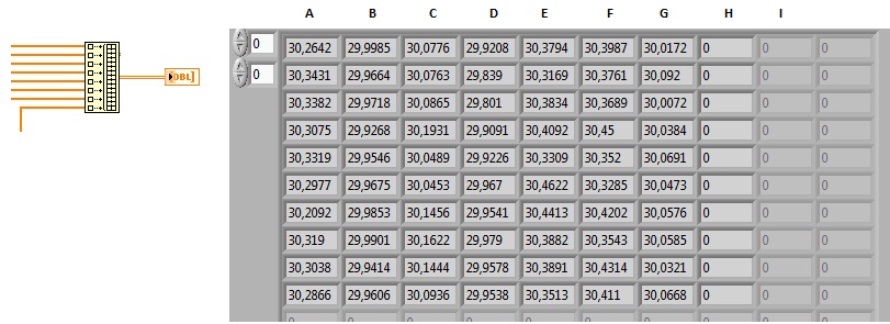
Thank you all for your replies, Ton's idea works but I notice a "display delay" when the waveform array data appear on the chart. When the 2d array is connected to the chart the data appear to move faster. Darren's article is very interesting, how do I plot an array of clasturs of arrays into a chart? Antoine's idea creates zero columns like 1 & 2 where as I would like to create columns like 3 & 4:
-
Hello, Thank you for your reply, No I do not call this .vi Should I? In MAX if a device is reserved then I cannot acquire any data from it. I tried using the "DAQmx Reset Device.vi" and after 1-2 runs it does reset the devices. What I would like to do is to "detect" when a device needs resetting and then perhaps use the "DAQmx Reset Device.vi". Thank you in advance,
-
Hello, I got 4 wls NI-9191 with the NI-9219 cards. Every evening when I leave the office I turn off the PC & remove the wls cards & router from the mains. In the morning when I turn on the PC and then the wls & router, MAX recognises the wls chassis but has issues seeing the NI-9219 cards. As a solution I reset the wls and everything goes well. Does anyone know why this is happening? Is there a way to programmatically reset the wls every time I start my .vi? Thank you in advance,
-
Hello, I am aquiring data from 8 channels (4 devices) so in order to plot them I added a build array (see attached picture) and created a 2d array. If one or more devices are switched off or disconnected this will create an array full of zeros (column H). How can I avoid this?

-
How to programmatically create multidevice tasks?
Ano Ano replied to Ano Ano's topic in LabVIEW General
Thank you for all the replies, Since I need to create a task for each device, are there any ideas on how to implement this in perhaps a "For Loop" and create an identical task for each connected device? -
Hello, I have 4 WLS-9191 with 4 NI-9219 cards and I want from each card to acquire 2 voltage and 2 Temperature (Thermocouple) readings. When I try to use this set up I get a "One or more devices do not support multidevice tasks." warning. The end goal is to programmatically create taks in such a way that if a WLS-9191 is switched on or off the program to detect it and either create a task for it or not. Any ideas on how to bypass this error?
-
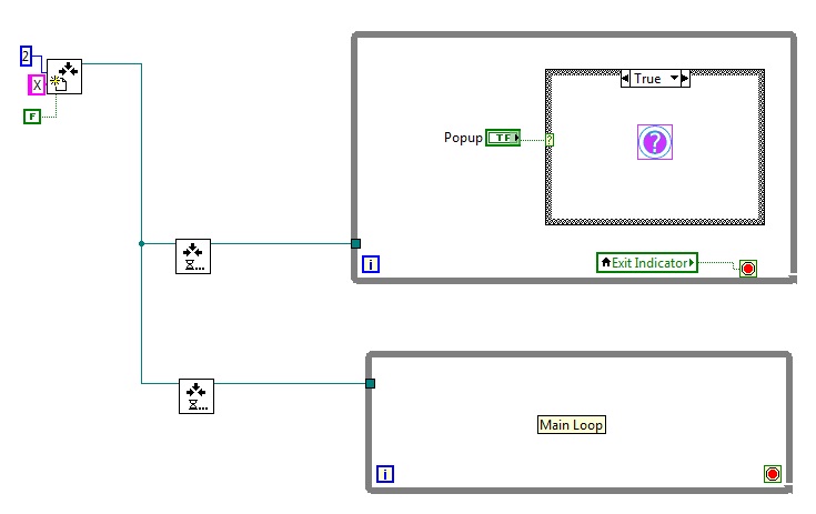
Hello, I have 10 while loops running in parallel and they are all connected with Rendezvous. 9 of the 10 loops operate fine but one of them does not work always. This 10th loop is a "popup" vi that when it gets a "True" value it runs. I also used probes and it seems that the while loop in question is getting all the rendezvous commands but when pressing the switch for the popup vi, the probe on that switch does not execute. For simplicity I am attaching a photo of a 2 loop Rendezvous, one with the popup vi. What am I doing wrong? Thank you in advance.
-
Update: The Pins 11-12 grounding removed the need of a startup software turning them off. Only pin 4 remains on during startup, all other ports after a brief on-off state (2"-3"), return to zero on their own. I am going to use Pins 6-9 (LEDs 5-8) but I am curious to know what turns on LED 3 (Pin 4)
-
Interestingly enough, grounding pins 11 & 12 removes the VISA error, BUT (there is always one:P)... when the PC starts the following take place: 1. All LED turn on for 2-3' 2. Afterwards all LED close except No3 which remains on During startup only the .exe closes all LEDs except No3 (Pin 4) (out of the 4 that I use). If I run the same program after startup (exe or vi) it closes all LED as its supposed to do!
-
I guess there is no way to bypass these security concerns? The VISA example (http://imageshack.us/photo/my-images/18/lpt1outalt.jpg/) produces an error on my PC. Not sure why...
-
Hello, It seems that the error that Labview produces is "−4850" which states that: "LabVIEW does not support this device driver on Windows Vista or later." This is strange though as the program works as a .vi but does not work as an .exe I am running LV2010.1 & Win 7 Is there a solution for this driver issue?
-
I am using as base code the "Out Port8.vi" (see http://imageshack.us/photo/my-images/708/lptoff.jpg/). Top part works when the driver is found. Bottom part is vice versa. I placed a small delay to give the OS some time to seek drivers and varied the time from 500 to 5000 and it did not matter much as it cannot located the drivers. as a .vi the program works perfect. as an .exe it does not. Why does it have hard time locating the drivers?
-
Hello, I built an application that turns off the LED and then auto-closes. I edited the registry so that it runs this application during startup. The problem is that the PC starts, the application opens and closes, but it does not switch off the LEDs. I think its because the drivers (NI? Win7?) may not load in time. Any advice/idea on how to tweek this and make it work?
-
Invert the output in Labview? Can I invert it via the motherboard/bios?
-
Hello, I need to programmatically set the chart x-axis to Zero time when the Labview software starts. Does anyone know how to do it?
-
The problem is that when the computer starts, it turns on by default the LED without me running the Labview software. How can I change this?
-
Indeed it is! I got the parallel port working (for the serial port I could only control one LED). I had to go to bios to tell it to use only the EPP for the parallel port (LPT1) http://imageshack.us/photo/my-images/267/parallelport.jpg/ The problem though is that when I boot/start the PC, the port automatically turns on all LEDs. How can I "tell" the PC to keep the LEDs "off" until I use them in Labview??
-
WOW Thank you for all these replies! Can Labview control the LED's via the PC parallel port (old printer port)?