
codcoder
-
Posts
74 -
Joined
-
Last visited
-
Days Won
2
1 Follower

Recent Profile Visitors
7,271 profile views


codcoder's Achievements
")


-
 Oh yeah, maybe I should have added that I work and live in a country in northern Europe.
 -
NI hardware has a strong foothold at the company where I work. Ironically people who are not programmers often see the value of LabVIEW, but because it is such a niche, it is difficult to find new people who are interested in working with it. Many traditional software developers see it as strange or unconventional, and that perception often influences discussions and decisions. And don't get me started on the fact that it is Windows based. Since we use the NI ecosystem, TestStand and mostly C-based instrument drivers, LabVIEW is always available as an option. So I do what I can to advocate it for it as an option when it fits the problem, and I've had some success, particularly with NI's FPGA solutions. But even I get that if it can be done in Python, and there is no special win with LabVIEW then, well, maybe Python is the better option? Today, though, most of what I do is built around TestStand, with a LabVIEW built supporting library. That is probably the future. And maybe RT-based solutions. But LabVIEW based stand-alone applications with in-house built click GUI's are probably a dead end. I don't see the future there at least from my point of view.
-
A follow up on this: the issue seemed to be with the PXIe-7820R module. We tried another one and it worked. Don't know why. Physical damage? Firmware mismatch? I have no idea but it is annoying since the module was brand new. But my specific problem is solved now.
-
Thanks for the input. I'll look into it. I would like to add that I have created a small test application which I also have sent to NI as part of the support task. This test application works just as intended on my old PXI system: an indicator on the front panel updates from a counter on the FPGA counting up when the trigger comes. But it does not work on my new system. The indicator is always zero.
-
Hi, So this is a blatantly repost from the discord channel but I'm getting kind of desperate here. I have opened an issue with the NI support function but I figure I might as well try the rest of the community here too. This is a copy and paste of my problem description which I have sent to NI and it is very similar to what I have written in the discord channel: I am building a new PXI-based test system that duplicates an older system which has been working reliably since around 2019. The purpose of this setup is to provide absolute time to an FPGA so that all FPGA read/write signals can be timestamped correctly. The timing architecture is as follows: A PXI-6683H generates a custom 1 Hz pulse using NI-Sync. This pulse is routed over PXI_Trig0 on the backplane. In the LabVIEW RT application, on the falling edge of the pulse, I write the next whole second value to the PXIe-7820R through a front panel control. On the rising edge, an FPGA loop is expected to trigger, latch that value as valid, and update the FPGA time function. Between pulses, the FPGA time is advanced using the FPGA internal 40 MHz clock. To verify that the FPGA loop has triggered, the FPGA sets a status indicator to 1, which I read back from the RT side. In the failing system, this status always remains 0. I also observe that other FPGA functions appear inactive. Based on this, my conclusion is that the FPGA is not seeing the trigger, or is not responding to it. Important context: The same software and FPGA firmware concept works in another chassis, a PXI-1062Q. The new system uses a PXI-1084 chassis. I am aware that the PXI-1084 is divided into three trigger bus segments, but both the PXI-6683H and PXIe-7820R are installed within the same segment. I have verified that the PXI-6683H can generate a signal. In MAX test panels, I can successfully drive PXI_Trig0 from the 6683H and read it back using MAX functionality, which suggests that the 6683H is operational and that PXI_Trig0 exists at least in some sense. I have formatted the RT controller and reinstalled software, but the issue remains. My main question is whether there is any chassis-specific routing limitation, configuration requirement, or compatibility issue in the PXI-1084 that could prevent a user-generated PXI_Trig0 signal from being seen by the PXIe-7820R, even when both modules are in the same trigger segment. So... anyone? I am hoping for a super obscure yet super easy solution here.
-
Aren't DVR's just LabVIEW's take on pointers?
- 14 replies
-
- 1
-

-
- dvr
- ni software
- (and 2 more)
-
There should be a way to work with very large files in LabVIEW without having to keep the entire file in memory. Many years ago I worked with a very large file in Matlab (well, back then it was a very large file) and I extensively used the function memmapfile: https://se.mathworks.com/help/matlab/ref/memmapfile.html It is a way to map a file on the harddrive and access its content without having to keep the entire file in workspace memory. A bit slower I assume but far less load on the RAM! There must be a similar method in LabVIEW. EDIT: I found this old thread: https://forums.ni.com/t5/LabVIEW/Is-there-a-way-to-read-only-a-portion-of-a-TDMS-file-without/td-p/1784752 This is something similar to what cordm refers to: Best practice regardless of language must always be to handle large files in chunks.
-
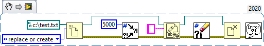
Actually I am not. I just added the constant "c:\text.txt" to this example but I have confirmed that I have write privilege to the folder on my computer.
-
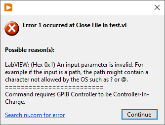
Hi, So I had a bug I couldn't figure out. The setup is according to the attachment. The Close File function kept throwing an error (code 1) and I couldn't understand why. But then I finally understood: if there is an error in to the Write to Text File the file refnum becomes invalid. The reason I am starting this thread is that I always thought that there is always a case structure in a sub VI, even for the primary functions, so that if there is an error the function isn't executed BUT any refnum passes the VI unaffected. But that isn't the case? Is this an expected behaviour?

-
Doesn't sound too hard?
-
Jake: Your Smarter LabVIEW Development Assistant
codcoder replied to jcarmody's topic in LAVA Lounge
Promising! But I am waiting for Jake to be able to produce VI snippets. Asked for a for loop and all I got was simple ASCII art. +------------------------+ | +------------------+ | | | [ ] | 0->1->2 | | | | For Loop | | // 5 iterations | +------------------+ | | Iterations | +------------------------+ -
Wow, thanks! This is exactly what I was looking for!
-
Hi, So I have this project with a lot of vi's which are saved with block diagram windows somewhat larger than the actual block diagram. I am looking for a way to programmatically go through all these vi's and resize the block diagram window size to the size of the actual block diagram (plus some margin). Has anyone done this? I'm looking at the different properties: BDWin.Bounds, Diagram.Bounds, but I can't really make heads or tails of it.
-
Can you put the AI node inside a single cycle timed loop with a slower clock? On my FPGA target, 7820R, it is possible to create derived clocks with both lower and higher frequency compared to the base clock of 40 MHz. Create a derived clock of 500 kHz -- if possible -- and connect that clock to the SCTL. If the compiler doesn't complain it maybe should work?
-
If you have a controller in the PXI chassis it can either run LabVIEW RT (used to be a PharLaps derivate but they are now switching over to something built on Linux) or Windows. If you want the PXI system to run as an embedded system, and if you need any real-time capabilities, then LabVIEW RT is the way to go. If you don't need that I do not suggest running Windows on the controller. We have a system where we do that and unless you really don't have space for a rack computer or some other external PC I don't see any advantages. What you get is basically a more expensive computer with worse performance. Just connecting to the PXI system with an MXI link is much better (which we do in all our other systems) and if I understand you correctly that's already your idea.