-
Posts
158 -
Joined
-
Last visited
-
Days Won
20
Content Type
Profiles
Forums
Downloads
Gallery
Everything posted by Benoit
-
Sorry, I do not have any 1-Wire on hand right now. I can't reproduce what you are explaining to me. The only thing I know, is that last time I used it, it was on a windows 10 PC x64 and x32. I was working like a charm...
-
I don't know what can cause this error. are you sure that the error comes from this library? Use the debug and find from which VI the error is generated.
-
Thank you for your answer. But, where do I find the style ID?
-
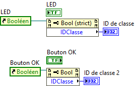
Hi all, I am trying to find a way to differentiate the various Boolean control trough property node. As I found out, there is only one ID class:8 for all of them. Is anyone have a solution for that? Thanks
-
Hello Mike, It's been a while I created this library. I was never a big fan of the file function. So I never used it. I am afraid you will have to do some coding and research. Benoit
-
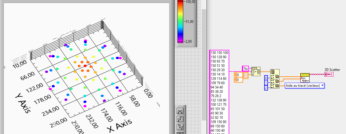
OK I see... so i am still stuck without solution. since my matrix is not complete, and there is no extrapolations, The only thing i found is the point like this... It's better than nothing
-
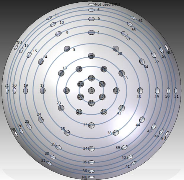
Hi, I can't understand how 3D graph are working. What I am trying to do is to plot multiple point XY with a Z as intensity of the measurement. I was expecting a x,y,z coordinate, but 2D for the Z... I just don't picture how it works. I got a half sphere with sensor. I am trying to represent in 3D X,Y the position of the sensors as a flat position ignoring the Z and using the Z for the sensors values. Please help.
-
I am sorry, but I do not have access to LabVIEW anymore. I can't do any conversion.
-
I never tried it without installation of the driver. in some case it might work like the serial port version. Benoit
-

[CR] 55 easily distinguishable color.vi
Benoit replied to Benoit's topic in Code Repository (Uncertified)
I think you posted in the wrong place. But there is where to start. Install the firmware in your Arduino +shield (Need to be GRBL 1.1) Then using the toolkit, you can control the XYZ plotter by giving the coordinate. This is not a G code interpreter, it is a tool to control the position of the XYZ.- 2 replies
-
- color
- distinguishable
-
(and 1 more)
Tagged with:
-
The sequencer that you use is it TestStand? Actually, The design I did give me more advantage than what is offer by NI. so no... I wont design it differently. When I want to add a Power supply model/manufacturer into the list, I have to modify only the middle lever of the HAL by adding a case in the list of every function. that case hold the driver from the manufacturer(LabVIEW,.dll or other) I can't show you by video right now. Not sure my company will allow me to do that. In the case of your sequencer, I believe that no other software will call your driver... I think that you can remove the VI server call layer. To keep the object in memory, you just need to keep the reference open. a getset can do that or I think if you use TestStand, it is possible to keep reference in memory as well, but I'm not sure. I didn't use TestStand since a while. the cost is too high and development time for the same test is to long compared with my test framework. Benoit
-
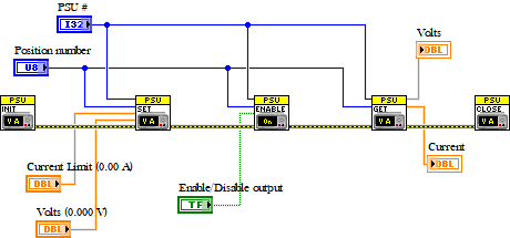
The call is done by the following step. Init: create a reference on all the function "VI" for that instrument. (keep in a getset) Function call: from get set use the reference of the function to send parameter or get parameter of the instrument Close: close all the reference from the getset In the .exe that holds all the Instrument, I have every instrument function in separate re-entrant VI. The physical init to the instrument and physical close instrument in done by the executable not by the caller. This allow the caller to have the status of the instrument initialization at every function call since I keep the error in another getset. The time to initialize the instrument is done by this executable, not by the caller. This architecture allow me to have an auto-recovery of any communication failure. This allow me as well to have only one prototype for calling any instrument that has the same function. Per example, the power supply 0,1,2,3,4,5,6... all have enable output function. by setting the PSU# at the function call, I can do whatever I want on whatever instrument... I do have 4 layer on my HAL, but the two other wont be necessary for you I think. The two other layer are Communication layer. ( a power supply can have 3 different output physically. I can access them virtually at the same time by different VI server call without sending 3 command at the same time on the serial port. (I made a queue at this level) Position Layer. The position layer is that I have a test framework that allow me to use in batch mode, unit mode or even asynchronous mode testing anything. per example, if I have 16 position on my tester that is used by 16 different .exe, I don't want to program differently the 16 .exe. I just add one layer with a config file that tells what position use what PSU# per example. So yes... crazy design, but if you can see what i can do now... FCT, Burn-IN, Programming, Hipot station and much more all with the same GUI. Only the test sequence (.exe) are called depending of the product I want to test. The product is selected by the serial number and a call to the MES system. That allows me to test different product part number and version on the same tester and same GUI. 3 years design for this crazy system.. and now.. I cannot see anyone in the industry doing something better than that. A Product test development that use over 300 measurement point and 20 different instrument with various technology takes me only one week and it's deployed and validated in production. Benoit
-

Terminals can't pass current value in event case
Benoit replied to jackscl's topic in LabVIEW General
Here is the problem. When displaying in a Hex format, the update value while typing cannot be activated. Since the value is updated only when you click somewhere else on the front panel, if the first click is on the button COM Write, the value is updated after the Event mouse down is fired. Benoit -
For my part, I use VI server call per function per instrument. The VI that is dynamically is in another .exe. This .exe has all the driver for all the instrument. the instrument selection and availability is done trough a .ini file. currently I support 22 different hardware like JTAG, Eload, PSU, Hipot, I2C CAN bus, SPI, Oscilloscope, Switch, DAQ, Ethernet, serial port, etc... Each instrument type support multiple manufacturer and model. When a call is done by VI server, the capability of the selected instrument is evaluated and report an error if out of range. This is generally what I designer here. I decided to stay 100% LabVIEW.
-

sending labview data over internet to a android phone
Benoit replied to makka's topic in LabVIEW General
Yes, with a robot and a finger simulation hardware. Benoit -

Terminals can't pass current value in event case
Benoit replied to jackscl's topic in LabVIEW General
Please post your actual VI. This will allow us to see if there is race condition or other problem. Thanks Benoit -
Amazing VI, but very slow. It takes many second to parse 2 Mb of Data. Is it possible to make that multiple processing in some way? I cannot find another encryption that will work with the input and output of those. Did you follow 100% the standard? Thanks Benoit
- 7 replies
-
- aes
- encryption
-
(and 2 more)
Tagged with:
-
I didn't found what is the details of the standard that is used. ECB or CBC I cannot find any other external tool that will correctly decrypt the information correctly. Benoit
-
Good job by the way. Benoit
-
Igor, your link is down. Benoit
-
A simple solution for you would be to work with a copy of the project and then whatever you want except deleting... then no crash and you project original remain clean... by the way, project and library are only .xml files. Benoit
- 11 replies
-
- labview 2017
- labview 2017 sp1
-
(and 2 more)
Tagged with:
-
You might have some VI that are not saved may be read only that reference a VI in that folder even this VI do not exist... The question is why those virtual folder are empty? what is the last action before? It is possible that you deleted library as well that where on those virtual folder.
- 11 replies
-
- labview 2017
- labview 2017 sp1
-
(and 2 more)
Tagged with:
-
Are you sure it comes from that VI? As I understand this VI is called with different function on every call. the one that will be called the most will be "Log Data". So I strongly suggest to create a unit test with your VI called multiple time with this function to validate if the leak comes from there. But I am pretty sure not... What the rest of you project is doing? Other question... what is the file size generated? Benoit
-
I'll say that you understand how to add a value to make it move, but for the rest, the architecture need to be revised. Look at the example i suggested you. Benoit
-
Look at the LabVIEW example Dynamic Event Generation.vi And learn LabVIEW basic. I cannot give you all the answer to easily, where will be the fun to learn LabVIEW. Benoit


