hooovahh
-
Posts
3,477 -
Joined
-
Last visited
-
Days Won
299
Content Type
Profiles
Forums
Downloads
Gallery
Everything posted by hooovahh
-
That makes me think that maybe your role is more of an architect than a developer. I didn't find the CLD very difficult personally. It was just a single loop QMH using arrays of strings, and I finished early and spent the extra time double checking my work. The CLA I barely passed, and worked up to the last minute.
-

Error accessing site when not logged in.
hooovahh replied to ShaunR's topic in Site Feedback & Support
I've contacted Michael. -
Storing/Importing DAQmx Task Configurations
hooovahh replied to A Scottish moose's topic in LabVIEW General
I use MAX as much as I can. I try to not reinvent the wheel unless there are limitations that I really need to work around, and MAX just does so much that I try to avoid custom things. I'll still incorporate MAX in my application, by doing things like calling test panels to hardware to open, or creating and editing channels, tasks, and scales using a VI I posted here. But as for the tasks and how they work in applications. I'll usually make the tasks in MAX and test them there, then perform an export into an NCE file which can go along with the source code which explains how the channels are all setup. Then in application builder, you can specify this NCE file to be imported when the installer runs. I do however remember some issues with editing tasks that have already been opened. Like I remember having my software opening it, and then trying to edit the scale of a channel and having issues where the new scale wouldn't be applied until I closed and reopened my software. I must not have been stopping or closing all of the references to the scale, or channel using the scale and that might not be a real limitation of DAQmx but something to look out for. I've had no experience with INIs or XML as a result. -
I made a suggestion for this on the Idea Exchange to give more font control over listboxes and tables. If you want this you should go vote there.
-
Personally I think this is a good idea, and NI already is doing something similar by tagging NXG posts so they can be identified. I do think there are some issues with making a new subforum. One is if we do make an NXG subforum, then what happens when it isn't called NXG anymore? I've heard that some day NI will just call it "LabVIEW" and the LabVIEW we all know and love might be called something else, like "Classic LabVIEW". But then again that might not be for many years until NXG has functional parity with LabVIEW. There are also going to be times when a subject is about NXG and Object Oriented Programming, which subforum should it go into? Now we'd say NXG, but in a few years would it make more sense to put it in OO? Anyway I'll talk to some admins and see if we can agree on something.
-
Attached is an example that does this using report generation toolkit, but does it through ActiveX calls. I think this needs to be ran on a workbook after all other writing has taken place, because it does it on a per worksheet view. For me I had N work sheets already made, some with data, and some with charts and graphs, then calling this would set the text and logo to the footer. Saved in 2015. Footer in Excel.vi
-
Tortoise SVN. I've used Mercurial, and Perforce too, but SVN is the one I'm most familiar with, and the setup was stupid simple. I only use LabVIEW tools for performing a rename in a project and SCC at once.
-
The NI Package Builder is less of a replacement for VIPM in my opinion, and more of a distribution method for installing software in general. NI may mature their package manager to one day replace VIPM, but as it is now the NIPM is not so much focused on installing LabVIEW packages, as it is focused on installing software. Now LabVIEW packages can be software (of course) but you won't find things like palette editing tools, running pre/post install VIs, or anything LabVIEW specific at the moment. It is more like an app store, where you can one day search for tools network packages, or larger packages like NI DAQmx. This is how NXG is currently distributed by installing the NIPM, and then choosing to install NXG and its dependent packages. There is also an offline installer but I suspect it is still just NIPM with the NXG packages as an offline repository. Of course this also opens up the possibility of making your own packages and you can have the "Hooovahh's Awesome Program" package which may depend on the NXG run-time, DAQmx, NI-DMM, and NI-VISA. Then these packages can be included in an offline repository that gets installed, or (potentially) an online repository so users of my software can update to newer versions of my awesome program, or newer version of NI's packages if dependencies allow it. Because of this I highly doubt it will ever replace VIPM for current generation LabVIEW needs. At the moment this just doesn't seem to be what the NIPM is made for.
-
Yeah I remember you, I don't remember what I was drinking but I remember you. Glad you had a good time at NI Week and the BBQ. That project looks very cool by the way.
-
VIMs are amazing and will cause revamping of polymorphic reuse libraries. I did a talk on this in August at NI Week which covers XNodes and the second half talks about VIMs and this structure which was named "Type Enabled Structure" unofficially in 2016 when it was introduced. http://forums.ni.com/t5/2016-Advanced-User-Track/TS9451-XNodes-Treasures-of-Reuse-in-LabVIEW-s-Attic/gpm-p/3538650 As others have said it works like a disabled diagram, where it goes through trying to enable each case one at a time and will enable the one that creates no broken wires. This can mean even more reuse if you can make your code more generic to accept scalars or arrays as it does in this case. The structure itself is not official in 2017 and has some editor issues. The impression I get is that it is stable (I mean it has to be NI is using it) but only after the code has been written and compiled. It still has odd cases where when you are first developing with it, the VIM won't adapt the way you want, but I've found it works just fine with code that is written and tested
-
If you have an active SSP (not sure how you'd get NXG without it) then you should have access to the Self-Paced Online training. No idea how much it covers or how well it is put together. http://sine.ni.com/myni/self-paced-training/app/main.xhtml It looks like they have a Core 1 with Acquire Analyze Present, and another set of sessions on transitioning to NXG 1.0.
-
Not sure how a waveform can be patronizing. Especially when it is an opinion of my own, based on my observations of...myself. I'm not saying you are wrong (because you're not) but I am going to say you are seeming glossing over some of the positive things NI has been trying to do, to try to get into the cheaper hobbyist space. Buying LabVIEW home for $50, which comes with application builder, and can deploy to Raspberry Pis as a target is a pretty positive thing that NI didn't need to do, that doesn't add direct positive revenue in terms of hardware sales. And giving away the student for free is also nice. I can't speak to the Linux LabVIEW thing, other than I've heard its poor. My only experience with Linux in the last 13 years has been running Linux on NI hardware. It's not something I've seen used in the testing career path I've been in, and I haven't needed it for the hobbyist projects I've had. If Linux is important to you, NI is failing you because they seem to prioritize Windows. Anyway I don't work for NI, I don't need to defend NI, and I don't know what NI has planned for the future. I'm just trying to stay neutral and show some positives if some negatives are being highlighted (maybe I'm just on the sine wave coming down). But I am not denying the valid negatives mentioned here. I also want others to join in on the conversation. No one wants to hear me spew the same opinion in different sets of words over and over.
-
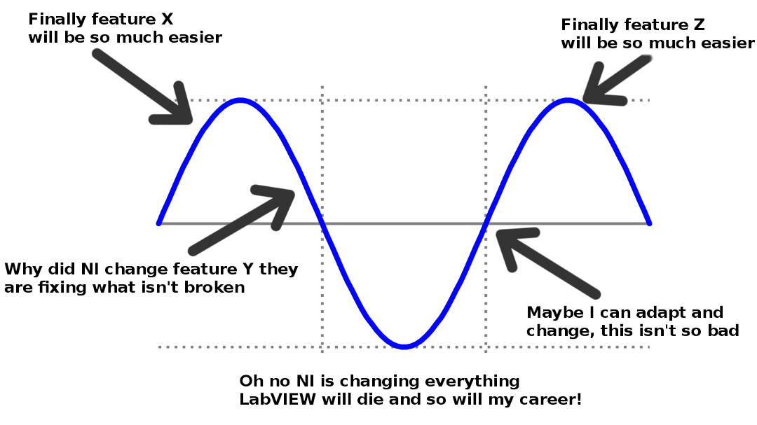
They're at NI marketing. I don't think anyone can make very well informed decision because so much of the platform is "Next version will have this feature, and fix this issue" and we can't really assess it until we have enough features to actually deploy a full real system, and find the things we like and dislike. I also have concerns about much of what you mentioned. I'll be presenting on NXG and 2017 in our next user group so I thought this might be a good time to illustrate what I call the NXG Cycle. The thing to keep in mind here is some at NI, and some LabVIEW insiders have been seeing NXG since 2013 or earlier. I've known about it but not for that long. 4 years or more of this cycle, all the while questioning all the current work you are doing and its relevance, can make for some very jaded feelings. You tend to stop having high highs, and low lows, and instead are just ready for it to be finished so you can deal with the change.

-
There certainly is a fine line between being on the cutting edge of a new version, and also being the first to find bugs and issues with a new version of software. I know a lot of companies that just hold off upgrading as a result. Most I know wait for the SP1 release of LabVIEW before upgrading at least. I like to participate in betas so the added excitement of new features, and thinking how I can improve my code with them is enough to help push me into the latest version. The message NI is trying to send with NXG is that it will replace the LabVIEW we know today...eventually. But that the information we all know about the language doesn't go away. Someone even mentioned how there is not going to be two different CLDs, one for LabVIEW, and one for NXG. You will be allowed to use either IDE because in the end they both are creating the same code. Things like data flow, graphical programming, palette navigation, and good coding practices like state machines, aren't IDE specific. That being said I know what you mean, there is some intrinsic knowledge about the current LabVIEW that will become obsolete, and we will need to learn about NXG's quirks. But honestly this is several years out, NXG 1.0 in my opinion is closer to Signal Express, than it is LabVIEW. But with each new version you will see more current gen LabVIEW features make its way into next gen.
-
You see people say this, but I'm not sure it will be true. The reason merge works on text languages is because sections of the code will be edited by different users. Maybe a subfunction in a file I modify, and a different function in a different section is modified by another user. The merge can then realize the changes between the two and make one file that contains both changes. The reason this works well is because in the file these two separate parts of the file are not linked and independent. I haven't looked at the XML structure much yet, but lets say each object has an offset from origin, telling it where it should be on the block diagram. If I perform a select all, and then move them one pixel to the right, every object in the file now has been modified, and it would be more like editing every line in a file in my text based language example. If you then make some other change to the code, the automatic merge will see we both changed the same line of code. And even doing this in a text based language means reviewing the changes and understanding how the merge should proceed. I suspect that in the real world parts of the file maybe modified in ways that effects lots of objects, which will complicate the merge. I don't think the XML file will solve our problems with automatic merge in SCC, but I do think it is an improvement over the binary blob of CG. Yeah I think NI had no choice when it came to the cost of NXG, they simply could not charge extra for it at this point. If it were a separate stand alone product, with its own cost and SSP, this thread would probably have a totally different tone. And as I mentioned already, NXG 1.0 is not a product marketed for us. If you are doing a simple USB DAQ with acquire, analyze, present, and you know your scope won't grow, it isn't a bad product. The integration of MAX features, is also pretty cool. For most things you shouldn't need a separate application to just confirm hardware is working, opening test panels, taking data, etc. Basic system integration stuff before you are writing code. Not that I had many complaints about MAX but I can see why you might want a single experience. Oh and I heard someone say that MAX isn't going away just yet. There still will be some features MAX does that the System Designer and NXG won't do. Not sure what the long term plan is.
-
While at NI Week I forgot to ask someone in R&D if they have been purposely providing one major new feature in CG (current gen is the term I've heard more often). And if so how long has that plan been around. VIMs are awesome and cool but has NI had that feature on their road map for 2017 release? And Channel Wires for 2016, right click 2015, etc? My only thoughts are I wouldn't be surprised if NI knew they had to have at least one new feature worth talking about each year, while resources were likely shifting to NXG. As for the message and release dates, I don't agree that releasing the finished product in 2020 (assuming parity is then with your example) would have been the best approach. Even with the non completeness, I can tell you I will be using NXG 2.0 (possibly the already released beta) for an actual real project. Until there is parity I don't mind using one IDE with its strengths, and the other for what it does well. Also I've actually heard some complain that NI didn't start putting alphas out and getting the opinion of others sooner. The thought process was NI maybe already made some key decisions before the those outside of NI could make suggestions for improvement. Now if NI was ready to hear that feedback, or make improvements based on it is another discussion.
-
About 10 years ago Michael posted a Lurker Roll Call thread that was pretty successful. After some discussion at NI Week this year several members said we should start a new thread for the users out there that monitor LAVA and use it as a resource, but for some reason or another just don't make posts, or join in the discussion very often, or at all. So tell us about yourself. How often do you use LabVIEW? What is your technical background? What is your favorite project you've done with LabVIEW? Ever been to NI Week or the LAVA BBQ? And if nothing else have you heard about LabVIEW NXG? NI has been teasing a new IDE for LabVIEW for a few years and 1.0 is finally out, what are your initial impressions? Also feel free to also post in the recent thread about NXG. I just did a search and over 30,000 users have 0 or 1 posts on LAVA.
-
Thanks Darren, I'd just like to add that these are useful for when you are trying to design more generic functions that can do different things based on different data types, or developing code that can works on data types in ways that would otherwise have to be hard coded. Here is a (poor) example. Lets say I want to write a subVI that will take in a cluster, and will increment every numeric in the cluster, but leave all the other data types alone. How would you do this? Well with these functions you can look at the Variant input, and determine what the data types are of the things contained in the cluster, and if it is a numeric, convert it to the numeric, increment, and put it back in the cluster. Certainly if you needed something like this you could write a static VI that works on your cluster but you'd need to create a new subVI for every cluster data type you have.
-
Yeah I haven't heard of Node-RED either but I saw it in action on the Teensy Audio System Design tool which sorta blew my mind when it first came out. It is a some what dedicated set of needs (audio processing) so the blocks are pretty intuitive and kinda does for audio what I think Vision Builder AI does for vision. And just like Vision Builder AI you can export into code which in this case is the Teensy C++ for the Arduino IDE. Interestingly enough 7 years ago NI already had a graphical programming language that ran in your web browser but it didn't catch on called Web UI Builder. I remember the first time seeing it and being confused why NI was developing what seemed to be a separate graphical programming interface which was vector based UI and had zoom of all things. Now we know, since Web UI Builder (as far as I know) was the first thing NI made which NXG was built off of. Interestingly enough Web UI Builder still works and runs in your browser but depends on Silverlight so IE only. It's also nice to see that NI didn't continue with the ribbon interface as shown in Web UI Builder.
-
A little while ago I posted some code on how to create boolean controls with images that scale well because the images are vector based and can scale up or down better than a static image like a PNG. After making that I made a utility that allows for selecting an image, and a control template and it creates the control. I showed this off to Danielle Hamburger and she encouraged me to clean it up and post it to the community. I'm still putting this in the In Development section just because there are several external tools needed that working around would be ideal if this were to be finished but for now it works and I use it often. So it works like you'd think. There is a library of vector images you select from, pick the one you want, then pick the Control Type (which is a folder of CTLs), then click create and it creates the control setting the decal button, VI description (adding License text if needed) and sets the icon editor icon. Dependencies If you just run the Vector Boolean Control Creator you'll need OpenG Time, OpenG File, and the JKI State Machine toolkit installed in LabVIEW 2015 or newer. The included libraries will work without anything else as long as you are in Windows (more on that later). If you want to include your own controls there are a few more steps and I left a text file explaining that in the Template Controls folder, but I included several already. If you want to add your own images I also left instructions in the Libraries folder. I wrote a VI that can convert from SVGs to the needed PNG and EMF files as long as you download inkscape (again instruction text files included). But inkscape is only a dependency if you want to use that utility to add your own libraries which are in SVG. Demo For good measure I made a Jing video showing how it works. Windows Only... So the Windows only part is an interesting one. I started with my UI being just a single 2D picture control and as you type your search in the top, it would go and open each image that matched the result, shift them into rows and columns, detect the number of columns shown, then detect and show mouse selection, and all the other stuff that would be needed. To say the least it was slow. I tried several ways to improve it, but in the end it was slow and I couldn't come up with a solution I liked. I could have added a search button but I really like the live search of typing it in and seeing it update as you type just like the icon editor glyphs do. So for a first release I went with the cheap and hacky solution and that was to leverage some .Net to embed a Windows Explorer window into my front panel, which is just the search results of a folder on disk. This now means you see the PNG images on the front panel, but it will only use that to show the UI to you, but then use the vector based EMF file when creating the control. Doing the search was a bit weird too since I couldn't figure out how invoke a search with the Explorer .Net so instead I wrote to a temp location a saved search that is XML, which I tell the UI to navigate to which then shows the search results. Oh and there is some .Net GDI resize going on so the PNG image is used as icon editor icon for the control but dependency could likely be removed with some G work. Anyway hope people find this useful. Vector Boolean Creator.zip
-
I also heard information like this. No one at NI specifically said this, but I got the impression that the extensibility will one day (hopefully) be at the point that a completely different IDE could be made replacing the existing one. If this is true then maybe this is what NI plans to do for the other platforms. I too am a bit surprised more importance wasn't put on cross platform up front, especially if his reasoning was for native looking UIs when NXG doesn't have a single system control. And yes I already gave this feedback to NI in person, and at the expo floor where there was a board to make UI suggestions.
-
Oh boy lots to take in (my own fault for not checking LAVA enough) Timelines are not published. If I had to guess (and I do cause NI didn't tell me) I'd say the current LabVIEW as we know it will be around for several more years. I wouldn't be surprised if the current LabVIEW still sees releases with new features and bug fixes through 2022, but again just a guess and NI them selves may not even know. There is a pane tool (at least on 2.0 beta I don't have 1.0) and you need to hold spacebar. Yes auto tool is the only option. I'm not thrilled with this but I understand and think I can get used to it. I was told by NI the 2.0 beta stuff can be discussed since it is in a public beta which doesn't require SSP or NDA so with that...it does have the HTTP functions in VIs and more importantly webVIs, but yes it is missing several other communications. Yes NI has a package manager and it seems to work pretty well so far with driver information and other larger installers. I'd assume you can have local repositories meaning offline installs. There is apparently some kind of command line interface for the package manager which will be useful for automated builds. As far as I know this is Windows only. Not sure if that will change in the future but certainly leveraging Windows UI components is going to make going to other OSs difficult. I did notice sluggishness but was told that might be a sign of VISA not installing properly, or thinking it is installed when it isn't. Hopefully a good install, with a several thousand VI project doesn't break things. This version of NXG probably isn't for the target audience of LAVA. We can use it and probably should if we want to give NI feedback, but don't try to migrate a huge project to it, it just isn't ready for most things yet. Still the Data Grid control is awesome (still needs work), WebVIs are awesome (in 2.0 beta but generates working HTML), and a vector based UI is greatly appreciated. Reception from people seems good. I think most get the message that current LabVIEW isn't dead, and that this is new but will be getting better.
-
LabVIEW EXE Running on a $139 quad-core 8" Asus Vivotab tablet
hooovahh replied to smarlow's topic in LabVIEW General
You should be using an event structure. If you use an event structure you can register for mouse down, mouse up, etc, or on value change. Then the event will be triggered on that event instead of polling a property node which forces a thread swap to the UI. Post your code if you can. -
Yeah for me the conditional disable says that OS is not a defined symbol and so it defaults to the default case which here is Linux. NI has lots of multiplatform code so you might want to look into how they do OS detection.
-
How do you make your application window frontmost?
hooovahh replied to Michael Aivaliotis's topic in User Interface
Works fine for me. I tried the set Top & Active in Windows 7 x64, LabVIEW 2016 32-bit. I had a wait which allowed me enough time to put other windows (non-LabVIEW ones) on top then waited and it was brought to the front most of all windows.