hooovahh
-
Posts
3,477 -
Joined
-
Last visited
-
Days Won
299
Content Type
Profiles
Forums
Downloads
Gallery
Everything posted by hooovahh
-
Sweet, look forward to seeing you again John.
-
Nope. I mean you breaking your NDA with NI is one thing, but an NI employee breaking their NDA with NI by posting on LAVA would be career suicide. If you have questions about super secret private special stuff, you should ask questions in the designated super secret private special forum.
-
We appreciate your activity here on the forum...but could you work on completing your thought. Is this an NI question? Is this a service and support question? If so contact them directly. Also it appears ass isn't on any filter of bad language so that's good to know.
-
Yeah there are aspects of the new forum I knew I wouldn't really like. There is a social network aspect, where you can write on eachother's wall. Or follow other users activity. I don't really need this but the integrated Chrome notifications is nice, and the updated mobile browser. The moderator tools are more or less the same, and Michael takes care of the high level stuff enough that I don't know the impact of the new forum but I imagine it is for the best.
-
Alot can change in 4 years, welcome back. Is this the first time you're seeing the LAVA face lift from a couple of years ago? What has kept you from LAVA (and/or LabVIEW)?
-

Lookup or add Variant attribute using IPE example
hooovahh replied to Michael Aivaliotis's topic in LabVIEW General
I saw some mild performance benefit from using the IPE for variant look ups instead of the primitives, but I remember it being a bit of a pain to test and use at times. I think something about creating an attribute if it didn't exist. Maybe it was just the way I was trying to use them. Edit: found my speed tests on the dark side for writing and reading attributes, it seems writing is going to be faster with the primitive, but a read that does nothing but return the value, is slower with an IPE than the primitive. Of course I'm sure NI intended on this feature being used where you perform a read, manipulate the data, and write it back in the same structure, which will probably result in even better performance. -
pxi-8430/8 f How to use PXI-8430/8 for simultaneous communication
hooovahh replied to sparu13's topic in LabVIEW General
So I've never used this particular piece of hardware before. But on Windows I have had a 12 port RS-232 serial device, connected via one USB to the PC and was able to communicate multiple ports in parallel. The solution for me was to use the parallelized for loop instead of plopping down multiple copies of the same VI. Right click the for loop and configure the parallization in your case setting the number of generated parallel loops to at least 8. Then use code similar to this with your subVI configured to reentrant of some kind. But honestly I can't think of a reason the parallel for loop would work, if your static declaration doesn't. Is there some other subVIs in your subVI that isn't reentrant? This could be a blocking call making all the other loops wait on each other anyway.
-
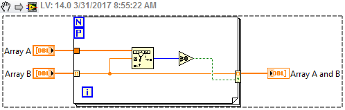
I'm not an expert at this type of function, but your version doesn't produce the same output as the others. In your VI I gave Array 1 = [4] and Array 2 = [5] and the output was [4,5], and the first VI posted here results in an empty array for that input. I haven't done any speed test but with the advent of the conditional indexing terminal I'd suspect the simplest solution to be the modified version of what SuperS posted. Edit: Oh but that does include duplicates multiple times. Maybe a remove duplicates from the Array B, or remove duplicates from Array A and B since that output will never be larger than Array B.
-
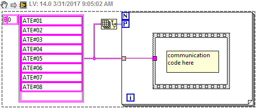
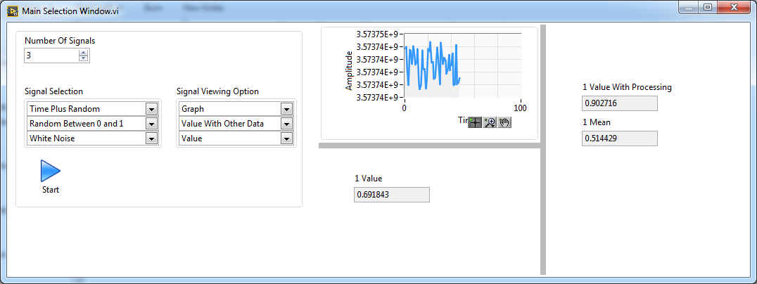
Demo time. So attached is what I was thinking. There are multiple ways of doing it I just went with the one I knew would work but might not be the best solution. Especially if the number of signals is more than 8. Run the Main Selection Window.vi. Then pick the number of signals between 1 and 3 (sorry I didn't do all 8 but I think you get the idea). Then for each of the 1 to 3 signals select the signal that it should be reading, and the viewing option which is either Graph, Value, or Value With Other Data which in my case is the running mean of the signal. Then click start. It will insert 1 of 3 VIs into the subpanel depending on the number of signals shown. In each VI is 1, 2, or 3 subpanels which inserts the core VI Signal Signal View 1, 2, or 3 times. This is the only VI that is reentrant. The benefit of this design is window resizing works nice. If you resize the main window all the sub windows get resized in real time and work pretty well without any extra code. I also included a queue to send messages to the independently running VIs. Right now the only command is quit but you could use this to send any data to one window, or multiple depending on how it is coded. Now actually getting your data being read in multiple instances may also require yet another parallel running task. If you have something like DAQ tasks all running on the same hardware, then you will likely need to publish that to a more global data space, so that each of the parallel running VIs can grab the signal they care about. In my demo I just used randomly generated data so each of them can run in parallel without having any hardware resource locking issues. Signal Selection Demo.zip
-
working with values of a table
hooovahh replied to rb767's topic in Application Design & Architecture
You already see how to work on individual rows. What do you mean avoid selecting the rows every time? Where in the code are you selecting rows at all? If you want a given rows values search for it. You see that the Add function already searches for Row Names that match the one you are trying to add, and you get an index of where the match is. Index the Y and C values at that found index and you'll have the Y and C values for a given row. If it returns -1 then there was no match. This add also won't add a new name if the name already exists. -
An expert could probably do it in a day or less. Someone new to LabVIEW might spend months and not get anywhere. It really depends on experience level and training. Think of it less as a front panel and more of a test application. How long would it take for someone to come up with a test application in other programming languages? Well if they have no experience in any programming language I'd say a very long time. The easiest solution is usually the least modular, scaleable, reusable, extensible, and eventually the most bug ridden and hardest to manage because requirements will change.
-
Dynamic (or semi-dynamic) UIs in LabVIEW can be a pain for sure. Years ago I attempted something called Multi Panel Interface. Don't look into using it, it was just a proof of concept. But my point is that the amount of development in making this UI was a decent amount of work. For this I'd suggest starting with just one UI that combines all three views of a single signal into a window. Then you can use a transparent tab with each of the three UIs that you have now on their own separate tab. Your code can run and update the UIs on all three tabs all the time, but the user will only be shown one at a time depending on what they selected at the start. Next I'd look into using this in subpanels. So your one UI that works on a single signal can be reentrant and spawn all the clones you need. For your single UI that beings them all together you can have 8 subpanel controls that get moved and resized with property nodes. Or another solution might be to create 8 separate VIs each with one more subpanel than the previous, and depending on the number of channels selected, that VI can be selected. The benefit of this is you can have them all evenly spaced with splitting panes and have them fit to the pane so resizing of the main UI is already taken care of for you. Without this resizing would have to involve looking at the new UI size and resizing all the subpanels with properties again.
-
working with values of a table
hooovahh replied to rb767's topic in Application Design & Architecture
Thanks but I don't know everything. The community as a whole knows way more than just myself about the best ways to do things. Post here, or at the NI forums if you have question about the pros and cons of solving a problem a particular way. -
working with values of a table
hooovahh replied to rb767's topic in Application Design & Architecture
Why thank you. I've been using LabVIEW pretty much daily since college in 2004. If you do anything that long, and that often, you get pretty good. I often make the comparison to a welder. If you started mig welding in 2004 your first welds probably look pretty terrible (just like my code). But after doing it daily for 13 years you had better be pretty good. Then there's the fact that I actually enjoy programming in LabVIEW so I seek out new techniques and keep up with the community. Anyway enough about me. OpenG is a fantastic set of tools that every developer should have available to them. They are licensed under BSD which is a pretty relaxed license stating you can use it or modify it however you want, with only a few minor caveats. The code has been used and tested since version 5 (or older), but hasn't had any major updates in a while. Some of the most valuable are under File I/O, Array, and the Variant Configuration. Having a single function that saves a front panel to a file, and loads a front panel from a file can be very useful. Global variables aren't the only way to pass data around to other parts of the application. Native globals have their place but often times a more manageable solution is to use a functional global variable, VIG, or action engine. http://forums.ni.com/t5/LabVIEW/Community-Nugget-4-08-2007-Action-Engines/m-p/503801#M240328 http://www.labviewing.com/fgv-in-labview/ http://forums.ni.com/t5/Example-Programs/Basic-Functional-Global-Variable-Example/ta-p/3503982 Like in this case I could see an action engine that has a Load, Save, Read, and Write method. Other options for passing data can involve references like a queue, or in modern versions the channel wires. -
working with values of a table
hooovahh replied to rb767's topic in Application Design & Architecture
I found several other suggestions. Control labels should be unique Control terminal labels should always be seen. Overuse of local variables Use of native global which doesn't seen necessary here Use of scalar data when you want it to grow as needed (meaning arrays should be used) Use of sequence structure Attached is a re-write that uses a state machine and no local or global variables. For the saving and loading I highly recommend getting the OpenG Configuration File palette which allows saving any data time into an INI file, in this case I saved the Y C and Row Names. I also added the Add button which makes a new row. If you don't have the OpenG you can replace this with your own custom VIs that reads and write arrays of strings. Subvi_WCS Hooovahh Edit2.vi -
working with values of a table
hooovahh replied to rb767's topic in Application Design & Architecture
Seems to work for me. There is quire a bit of inefficient ways of doing things, but the work of clicking Set Y or Set C does set the cell value leaving the rest. Am I misunderstanding what it should do? EDIT: Okay I see the problem. So in case 1 of the sequence structure add a Transpose 2D array after the second build array, if you probe this you'll see the array only has two rows but 6 columns which is the opposite of what you want. Then the next issue is in case 2 where every time the VI runs you are initializing the array (outside the sequence structure) be be empty. What you probably want is to use a local variable on the WCS and wire it to the shift register in case 2. Then the newly loaded (and transposed) values will be used and will be replaced when you click Set. -
What have you done? Post your code, show what you've tried and explain where you are having issues. Beyond that here is some code that is a marquee with scrolling letters. http://forums.ni.com/t5/Example-Program-Drafts/Moving-Message-Board-Example-Code/ta-p/3494437 http://forums.ni.com/t5/LabVIEW/Labview-Marquee-Help/td-p/2716369 And in the future be sure and use a more descriptive title explaining what you are doing instead of saying Hi.
-
That's how I do it on my Linux RT based cDAQ. Drop down a System Exec function and give it this string on the input to the Command Line: unzip "%s" -d "%s" Where the first %s is the path input to the zip you want to unzip, and the second is the path input that is the directory of where you want the zip to be extracted to. Looking at my code I also provide the Working Directory as the folder that the zip resides in but I think that is unnecessary. It is a bit disappointing the NI and OpenG compression utilities don't work on the Linux RT, but wrapper VIs could be made on the system exec and get similar functionality. If you SSH into the system you can get help on the unzip and zip functions showing the various command line options.
-
Version 1.4.1 is on the tools network. I just opened VIPM and it told me there was an update for the UI Tools package. The version listed here on LAVA still looks like 1.4.0.
-
Yeah it is unchanged from the version posted in the thread I linked to from over a year ago. But I still had plenty of people find that thread, and then try using all the broken versions so I figured I'd get around to putting in the code repository. Glad you like it, hopefully some day we won't need it.
-
Version 1.1.0
477 downloads
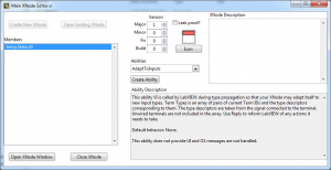
8 Years ago the first version of the XNode Manager was posted to the code repository in an attempt to allow the editing of XNodes. Being a fan of XNodes, but knowing that the XNode Manager is pretty limiting because of its age, I set out to make a new version with similar functionality. The XNode Manager had a blank XNode, and blank Abilities that it just made copies of. This is fine but then the abilities and XNode are quite old. There were many new Abilities added since version 8.2 and you can't add them using the XNode Manager. My XNode Editor reads your LabVIEW resource and populates the list of abilities to create from the ones that are possible to create. Then VI server is used to create the XNode, State control, and Abilities. This sets up the connector pane like it should and should work with all future versions of LabVIEW, until NI changes something that breaks it. It also reads in the XNode Ability descriptions to help understand how to use the new ability VIs. In addition to being able to create and edit XNodes, you also can edit the XNode icon, and description, along with adding any new abilities. Be aware this uses several private functions, and several undocumented features that could be potentially bad. I did a decent test to make sure memory leaks weren't a problem and I made several XNodes and Abilities and it seems stable. But at the end of the day if it blows up and crashes, don't be surprised, you've been warned. The original thread with discussion and progress on this tool was started here. -
View File XNode Editor 8 Years ago the first version of the XNode Manager was posted to the code repository in an attempt to allow the editing of XNodes. Being a fan of XNodes, but knowing that the XNode Manager is pretty limiting because of its age, I set out to make a new version with similar functionality. The XNode Manager had a blank XNode, and blank Abilities that it just made copies of. This is fine but then the abilities and XNode are quite old. There were many new Abilities added since version 8.2 and you can't add them using the XNode Manager. My XNode Editor reads your LabVIEW resource and populates the list of abilities to create from the ones that are possible to create. Then VI server is used to create the XNode, State control, and Abilities. This sets up the connector pane like it should and should work with all future versions of LabVIEW, until NI changes something that breaks it. It also reads in the XNode Ability descriptions to help understand how to use the new ability VIs. In addition to being able to create and edit XNodes, you also can edit the XNode icon, and description, along with adding any new abilities. Be aware this uses several private functions, and several undocumented features that could be potentially bad. I did a decent test to make sure memory leaks weren't a problem and I made several XNodes and Abilities and it seems stable. But at the end of the day if it blows up and crashes, don't be surprised, you've been warned. The original thread with discussion and progress on this tool was started here. Submitter hooovahh Submitted 03/15/2017 Category XNodes LabVIEW Version
-
***Experimental*** Control References XNode
hooovahh replied to DTaylor's topic in Code In-Development
Neat concept. One of those reuseable functions I've had for a while can get all references to controls on the FP given a VI reference, and the name of the control. This works alright, but the control references are of the control class and not the more specific class like String Control. I improved on this with an XNode that still does searching for controls based on their labels, but you can specify the control class to cast it to. Still in some cases I think I like yours better. If I needed to do an operation on all booleans I'd use mine since it returns an array of references, but yours is pretty damned simple. -
But yes your points are valid about the classless nature of my example. VIMs (which can work better with classes) might open this up to a few more possibilities where XNodes fail. And as for the UI I had never thought of that, and never thought I needed it, but I admit I could see a few places where that type of functionality could be useful.
-
Oh but they could. Look at my circular buffer XNode example. It is an XNode but it could still be used as a VIM. It bundles a DVR with some information, and the data type you want, and then the other functions change the data type of a control or indicator, based on the DVR. So what you have is an Init function where you define the data type (like obtain queue) and then the read returns that same data type (like dequeue)