Search the Community
Showing results for tags 'vision'.
-
Hi everyone, I am trying to watch a process and record video of it sometimes. So I need a button that starts recording and then stops it. And again when I click start it should create a new file with new name. I have tried it in different ways, putting create file inside case structure and outside of structure etc. But I am either getting only 1 video(which overwrites), or just pictures. Lastly I have tried with shift register and got this error: Error -1074395995 occurred at IMAQ WriteBMPFile I would appriciate if you could help me. Basler Camera labview.vi
-
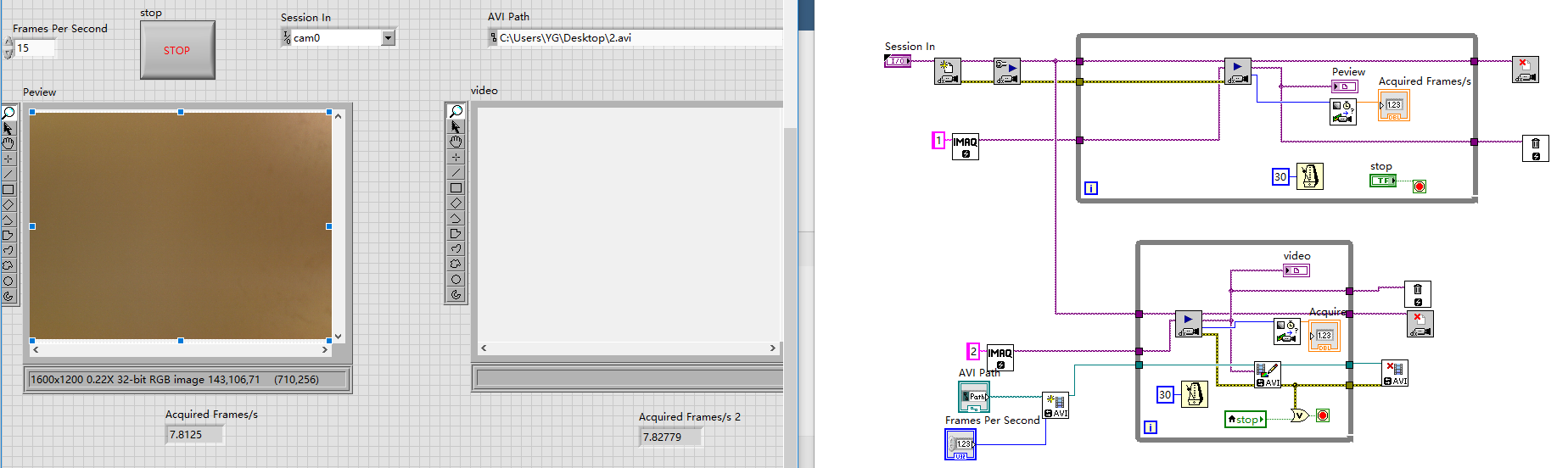
Hello, everyone! I want to synchronous acquire and save video files via a GIGE camera while not influence the frame rate. I achieve the program as below, but the frame rate is highly unstable. I hope you can offer some ideas, thanks!

-
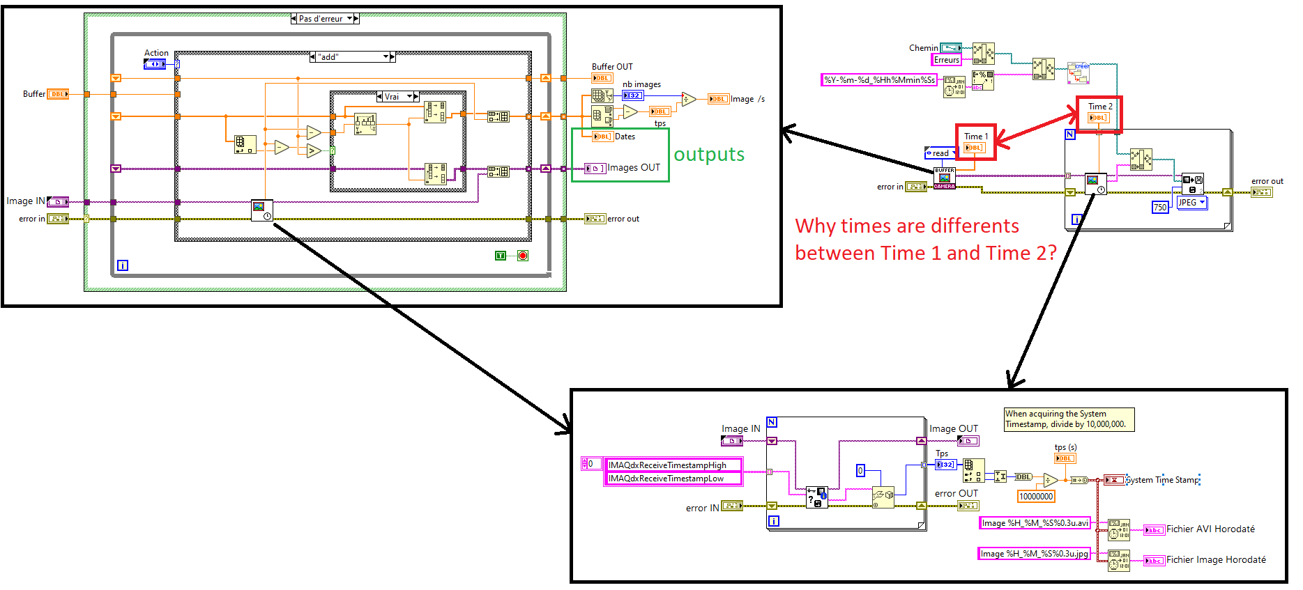
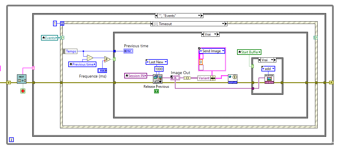
Hello, I have a GiGe camera Basler. I have created a ring acquisition like the exemple IMAQdx with circular buffer. I load an image every 15ms and I add it in a Vi type FGV (cf. Stock Images.png). In the FGV vi, I create 2 tables. One is for the timestamps and the seconds is for the images. I use the timestamp table juste for keep the last 15s. If my test crash I save the images table. If I use the Vi to look at the timestamp of my image table, it is not the same timestamp as when I added the image in the table (cf. Save Images.png). Why? The propreties IMAQdxReceiveTimestampHigh and IMAQdxReceiveTimestampLow are not attached to the images? I hope you understand my English 🙂 (thank you deepl) François A.
-
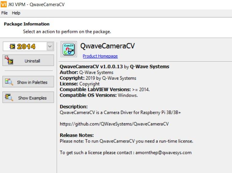
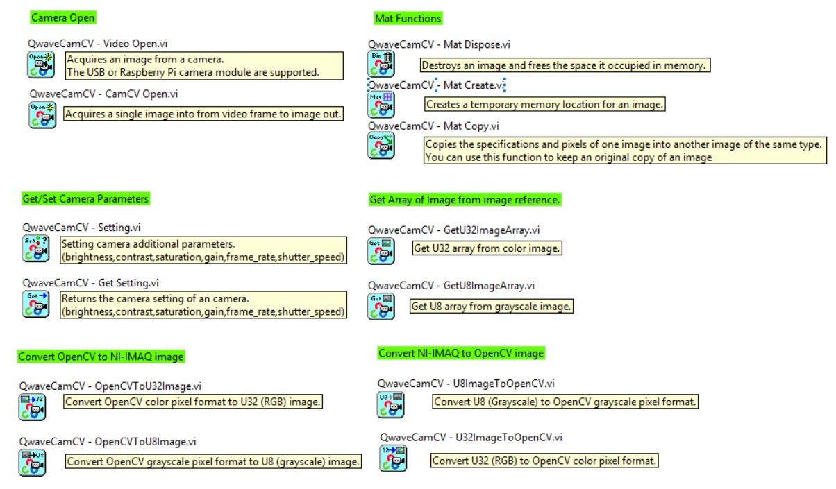
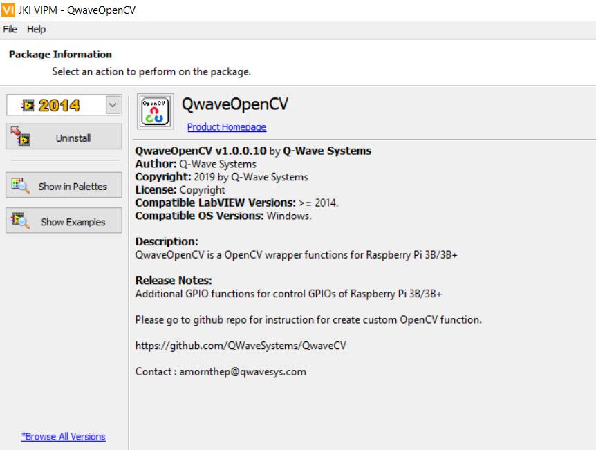
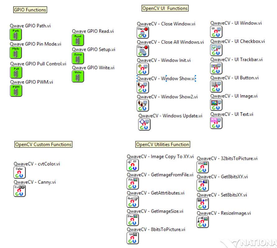
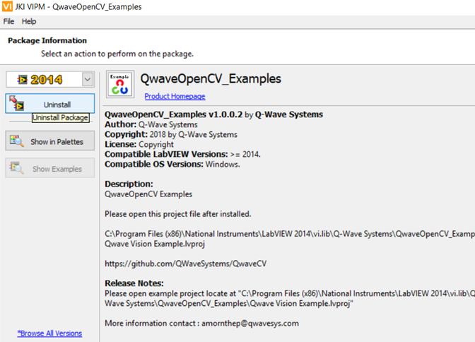
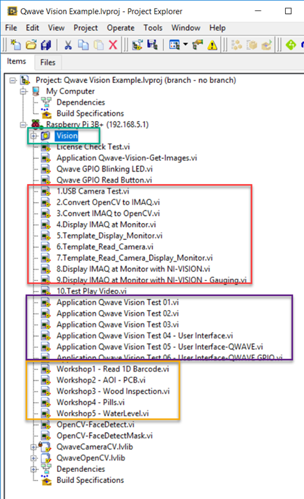
 New Toolkit : OpenCV wrapper for Raspberry Pi (LinuxRT) for LabVIEW Great ! learning platform student and maker for learning machine vision application with LabVIEW. It's working with LabVIEW Home 2014 edition and required LINX 3.0 toolkit. You can run NI-VISION toolkit with Raspberry Pi board too. 1.QwaveCameraCV is a LabVIEW Camera Driver library for Raspberry Pi 3B/3B+ (LinuxRT) https://github.com/QWaveSystems/QwaveCameraCV 2.QwaveOpenCV is OpenCV wrapper functions for LabVIEW for Raspberry Pi 3B/3B+ (LinuxRT) https://github.com/QWaveSystems/QwaveOpenCV 3.QwaveOpenCV Examples using OpenCV (C/C++) and NI-VISION for Raspberry Pi 3B/3B+ (LinuxRT) https://github.com/QWaveSystems/QwaveOpenCV-Examples
- 6 replies
-
- 1
-

-
- vision
- raspberrypi
- (and 1 more)
-
Hello, I need one help regarding changing the image image type How can I convert grey scale image to false color image? Here, I have attached two images. 1. greyscale image 2. is just an example that I want to convert. (False Color). Any help would be appreciate. Thanks, Parth Panchal
-
Hello All, I am new to the camera labview programming. For my research work, I am using camera to grab the live image. I am stuck with one problem. how to treat the background? I tried to subtract the constant value from the entire image, but with that i am loosing few of my data. I know one solution, but I don't know how to implement this solution. Problem: how to take the values from the 4 corner of the image and subtract those value from entire image? If anybody previously develop similar stuff then please help me out for this. Any help would be appreciate. Thanks, Shaun removebackground.vi
-
Hello All, Did any one previously used Imaging source camera (DMK series)? If yes, then please give me a reply. I need one help regarding Camera Attributes. Thanks,
-
Hi to all. I would like to get the number of white pixels in an image (so get the white area). I see histogram.vi but I do not know how to do that. Any help? Thanks a lot!
-
I would like to know if there is a parameter in line scan camera which allow me to control time trigger along NI MAX or labview with imaqdx. I mean, I would like to triggering camera during 100ms which specific shutter and specific line/sec. And if I change shutter or line/sec the time trigger keep being the same (100ms) I don't know if this is possible with some parameter of line scan camera. Thanks a lot.
-
Hi to all, First of all thanks a lot for reading this post and being able to help. I am trying to use Imaq Compare Golden Template vi in a for loop. I am trying to do the next: 1- I have 3 templates and 1 image inspection. 2- The templates are in the image inspection. So image that the image inspection is an image with a big 1 2 3 numbers. So the templates are 1, then 2, and then 3. An for loop has 3 iterations. 3- In each iteration I pass a template, with IMAQ pattern matching vi template is found in an image (getting bounding box) and then do the compare golden template to get the defects (differences between template and image). I am doing the program based on this example "LabVIEW\examples\Vision\Golden Template Comparison\Golden Template Inspection.vi" My program is the next: In the program I have three images (Cam1_PROD_display, Cam1_PROD_display2, Cam1_PROD_display3) with defects drawn in each templates, I mean, defects in template 1 are drawn in Cam1_PROD_display, defects in template 2 are drawn in Cam1_PROD_display2, defects in template 3 are drawn in Cam1_PROD_display3. Something like this: -Templates are three (1, 2, 3): - And the displays Cam1_PROD_display, Cam1_PROD_display2, Cam1_PROD_display3 show the next in each display (with defects in red): - But I want just one display which shows all defects in one image like this: How can I do that with the code that I have? I think that I have to do some operations (merge) of the three displays in one. Any ideas? Thanks a lot.
-
I have a LabVIEW based application for Vision inspection system. My application consist of acquisition from 6 cameras. My question is which solution is good 1. 6 Cameras connected to single PC1 or 2. 3 Cameras connected to PC1 and other 3 cameras connected to PC2 Brief explanation on your answer is appreciated
-
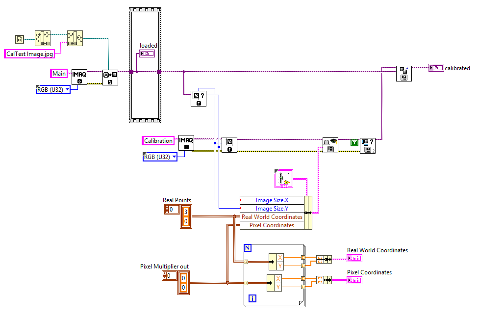
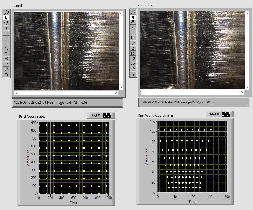
Hi I have a camera set to observe an inside of a pipe. Because I know the angle of the camera and where is it situated inside the pipe, I can produce an array of points that correspond to specific pixels. Because the camera can move up and down and change the angle, I have to do it dynamically, so I can't load any calibration template because the calibration is changing on the spot. So I've managed to create the calibration points and pixel points, but after using them in Learn Perspective Calibration.vi image doesn't change. See .zip attached What am I missing? Please help caltest.zip
-
Hello to all. First of all thanks a lot for reading this post and being able to help. I have noticed the next problem: My application has a camera, this camera takes images (snap mode) and application process them (detect some edges in the image). It works fine. But when I make the Display bigger my application takes longer to process images (and for me that is crucial). I think that this happens because my application in this case has to process a bigger image (bigger display = bigger image??) So maybe if My camera takes images with lower resolution I solve the problem. So how can I change image resolution captured by my gigE camera? In NI MAX or in Labview? Thanks a lot!
-
Hello to all. I am using NI MAX to get images from a camera (snao mode and hardware trigger). The camera is a basler 1300-30gm. The problem is the next: My camera snaps 4 images (1 image each 40ms). In pylon viewer (camera oficcial software) I can see the four images correctly. The problem is that when I am trying to see the 4 images in NI MAX sometime the camera can not take the 4th image... like there is no time to take the 4 image (or process it to visualize in NI MAX). So maybe there is a configuration parameter in NI MAX to solve this. Any ideas? How can I solve it? I set up package size to 8000. Maybe package size is the problem? Thanks a lot.
-
Hello to all. I have an image and a ROI. I would like to get the minimun distance between the first edge and the last edge in horizontal position. See image attached. If every edges found are in color yellow I would like to get the distance between edges in red (minimun distance from last edge to last edge in horizontal direction. I have tried to use "IMAQ Clamp Horizontal Min VI" but this VI does't the option "from first to last edge" and the only way to get what I want is to play with contrast but it is not work for some of my images. So is there any way to get what I want? Here is the image. From fist edge to last edge I mean from left to righ, the first edge found and last edge found. Thanks a lot.
-
Hi to all. I would like to create an application where usar can train an OCR programmatically. So do the same that vission assistant when user trains OCR but in an application. So, take picture from a camera (I have already done this) then click button, select area to train and put the train (for example type "9" if the image is a number 9). And save it. And if for any reason PC is shutting down, application can remember the train. That is possible?' Thanks a lot!
-
Hello to all. First I explain my environment and then I will ask the question. PC 1 (development PC): intel i5, windows10 64bits, 8GB Ram, Labview 2015 SP1 (32 bits), Vision Adquisition Software 2015, Module Vision 2015, DSC 2015, ni OPC Server. PC 2 (deployment PC) : intel celeron 1.99 GHz, windows 7 64bits 8GB Ram, Labview 2015 SP1 (32 bits), VIsion Adquisition Software 2015, Module Vision 2015, DSC 2015, ni OPC Server, Run Time Engine 2015, VIsion Run Time 2015. PC 3 (deployment PC) intel Atom CPU N2600 1.40GHz, windows 7 64bits, 4GB Ram, Labview 2015 SP1 (32 bits), VIsion Adquisition Software 2015, Module VIsion 2015, DSC 2015, ni OPC Server, Run Time Engine 2015, VIsion Run Time 2015. I use the next in my aplication: 2 cameras GigE Lan connected to PC. A PLC connected RS232 through ni OPC server and about 15 shared variables. In development environment my application works well. In PC 2 a executable of my application works well. But the problem is that the same executable works bad in PC 3. Front Panel is slow and displays of image cameras don't refresh the image well. So all my application is slow in PC 3. What can it be? I don't think that it could be the specification of PC 3 but I don't know... Does anyone fix something similar? Any help will be appreciate it. Thanks a lot.
-
I would like to try and upgrade my current CCD (pretty close to 640x480) to a higher res model (1080p). Here are my two requirements: It has to work LabVIEW/Vision software (could interface through GIG-E/IP or whatever) It has to fit inside of a tube about this size: (marker for scale) http://i.imgur.com/9i8nPRE.jpg The housing tube can be increased in size up to about a 1.25" diameter the tube runs back 2' until it opens up into an open space where we have a gigabit switch. The camera could just have a telescoping lens or be small enough to fit in a tube that size with the cables running out the back of the tube. I have been searching Hobby sites and small electronic sites/stores but nothing has caught my eye yet. I am hoping someone here may be using some CCD (maybe for security reasons?) that does pretty close to what I need. Thanks for any help!
-
Good day, I am trying to find a way to remove staff lines from music score for further processing. I am working on OMR (optical music recognition). I am not sure if it is possible with labview but there are some similiar projects using opencv and python. but my work is based on labview. So i was wondering of i can actually use anything to get it done. I know the steps for staves detection using C++. 1. line detection (using histogram profiling or hough transform) 2. filter the line from original image my problem is that 1. I can use hough transform to detect line but theoritically it won't provide me with enough pixels to remove the whole staff but only a part. so I am wondering if someone has used histogram profiling to detect lines? 2. how to filter the line from original image? 3. any way to import opencv to labview? ( problem remains because i am using 64 bit system and can't call 32 bit .dll, really stuck on this one.) Thank you so much for any suggestions and help.
-
In my job I develop in-house machine vision and image processing solutions for my company. In industrial machine vision and inspection, there are several main players (Cognex, Keyence, Matrox, Halcon, etc.) LabVIEW and IMAQ are not totally out of the picture but are far from common for manufacturing applications. I try to use LabVIEW whenever I can because I find it's great for quickly prototyping proof-of-concept systems. I use the Vision Acquisition and Vision Development Module toolkits extensively. For the most part, the functions provided by NI meet my needs. Increasingly though, I find myself pushing their limits, and yearning for the functionality offered by some of the competition. In some cases I can leverage these external libraries but that can be cumbersome. Aside from a couple of older, paid LabVIEW libraries from third party companies, I can't find much out there to complement the IMAQ palettes. 1.) Are there quality VIs out there and I'm just not seeing them? 2.) Is there an appetite for them? 3.) Would anyone be interested in working (with me or otherwise) on an open-source image processing toolkit?
-
 Hello, I am having a bit of an issue applying a threshold to an image and getting reliable results. I am thinking using edge detection prior to doing any other image processing could make this work... but I am at a loss for how to implement it. If you look at the image below you will see the root of my problem. The top set of images and bottom are only a second or 2 apart but the threshold sees them differently, yet the edge detection seems to correctly detect the edges the same. I only care about the range of pixels that usually makes up the brightest part of the image (hence the thresholding) but the low end of that range changes from frame to frame and I am left with an incorrect determination. My question is, does anyone know of a good way to use edge detection (or maybe some other method that I am not aware of) to help me with this problem?
 -
 Hi , i am trying to find circle edge detection .. here i have to manully draw the ROI to decide which circle i need to find .. but in my case instead of drawing i need to enter ROI location manually .. is it possible ? i have added my code ProducerConsumerEvents 4 - Copy - Copy.vi
 -
I recently had a project dropped into my lap and have had a tough time finding information about it on the web. Here is a quick outline of my current issue. I am trying to take in an analog video signal (640x480) and process the stream in LabVIEW/IMAQ/IMAQdx (end goal would be to have uncompressed video being processed). I need to be able to have an uncompressed image to do calculations on. I am currently trying to achieve this by using an axis video server and converting the analog signal into a digital signal and finding the camera via an IP address (having networked video was requested as well... Not a must though). My understanding is that LabVIEW takes in the video stream as mjpeg (please correct me if I am wrong) and even at the lowest compression setting mjpeg streams are still compressed pretty heavily and use a lossy compression algorithm (again correct me if I am wrong) which will make doing any reliable image processing for me very difficult. So my question is... Is there a better way to do this using any other hardware? We will be putting the software on a pc like this, so I am unable to use pci/pci-e boards/cards but something through USB or Ethernet ports is fair game. I really appreciate any help I can get! I am using LabVIEW 2011 with Vision 2011
-
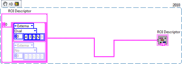
Does LabVIEW allow to define the parameters of the ROI descriptor during runtime? I need to make a calculation first and then define the descriptor.
-
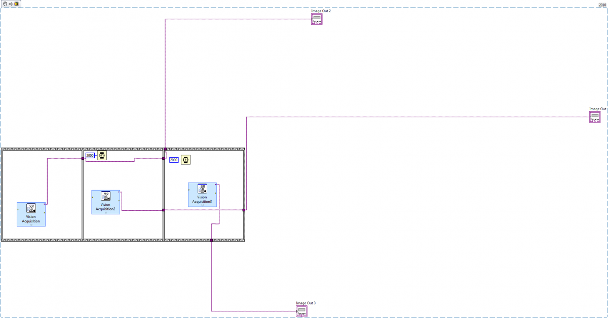
 I need to take three pictures with different exposure values. I used vision acquisition for this. I tried using the finite acquisition but I could not find a way to set a different exposure value for different pictures. I used the single acquisition 3 times in a flat sequence with 2 seconds of gap. When I take a test picture with vision acquisition it looks fine but when I run it in the program, they are not at all the same. Sometimes two pictures are the same, sometimes it is just white and sometimes the higher exposure value is brighter than the lower one. Help please