MikaelH
-
Posts
835 -
Joined
-
Last visited
-
Days Won
51
Content Type
Profiles
Forums
Downloads
Gallery
Everything posted by MikaelH
-

Database Connectivity Toolkit Multi Row Insert
MikaelH replied to lisam's topic in Database and File IO
Sorry, I don't remember how much faster it was. -
Database Connectivity Toolkit Multi Row Insert
MikaelH replied to lisam's topic in Database and File IO
I would use the low level SQL syntax to do this...if the database supports it. INSERT INTO test1 (Column1,Column2) VALUES(1,2),(3,4),(5,6); I've stopped using NI's DB toolkit, instead I use the LabSQL ADO drivers wrapped in my own driver. This is much faster. I've attached my version DB_Export.zip- 8 replies
-
- 1
-

-
- database
- connectivity toolkit
- (and 2 more)
-
Sorry, it's using lots of internal libraries, but I've attached the the same HTML report with the JS and CSS files externally linked (this is the default way we save the plots, we refer to all JS and CSS files from a server). In this version you can see how easy it is to use the JQPlot API Report.zip
-
BTW this is the end result with the VI above:

-
Here is a quick hack that does the job. I hope you have the Vision Sub VI, to find the Line Intersection point. I use that in combination with a OpenGDS VI to see if 2 lines intersect, sorry didn't have time to document it nicely. //Mike OpenGDS_LineIntersectLine.zip
-
Also can you add debug mode to the VI, so it can iterate through images from disk as well, and also supply those images. It makes it easier to help you with the task. I don't have a camera attached to my PC at the moment. Also a small description how your VI is supposed to work would make it easier to help you out.
-
The VI:Draw Geometric Matches Position is missing
-
No Worries, that's why we are here :-) The property node that will let you know the Coordinate Offset is a property node that is "Secret", you can only select this if you put this into your LabVIEW.ini file. SuperSecretPrivateSpecialStuff=True If you don't want you use this property node, you can just use a constant value.
-
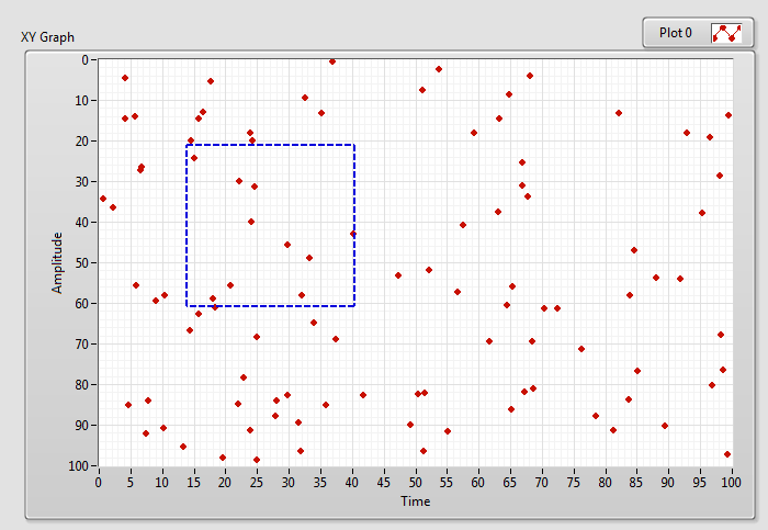
I've created an example for you. XY-GraphSelection.vi
-
Use the property node called: PlotImage.Front, this value accepts Picture control data.
-
To be able to do this, you need to have every point as a one plot, and then you can use the PlotImage.Front property node to follow the mouse to draw a ROI on the graph, and then find the plots-points that are within the ROI and change the Color of those plots. It might be easier to use a Picture Control Plot to start with.
-
If you want to access the same object from 2 different loops, you have to have use an Object By Reference solution. But you can use the Command Design pattern to send Object By Value from the producer to the consumer loop.
-
Action Engines... are we still using these?
MikaelH replied to Neil Pate's topic in Application Design & Architecture
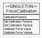
If I need something like the an Action engine (reading/writing some common data in different parallel VIs), I’ll always go with classes. And then of course it has to be by reference classes. Converting an Action Engine to a Singleton class is a solution I often use. I follow the Single Responsibility Principle, for a class like this.
-
Here is a quick example UDP_FileReceiver.vi UDP_FileSender.vi
-
Can you post your code? How big do you make the UDP packages? I guess you know that a one UDP package could only be 65,507 bytes So you need to split them into multiple packages with some header data, so you can see that you have received them all and put them together in the correct order.
-
You can have a second (or third page), hidden and change it so it becomes visible.
-
As always, thanks you, thank you, thank you.
-
See you there :-)
-
If I want to do accurate measurements I always go with a telocentric lens. Of cause to buy one that can cover 20” is too expensive, but maybe consider a smaller FOV and an XY stage/gantry for the camera to move around over the object.
-
I don't really follow, what is not working? BTW, after changing something under a class, you need to save the class.
-
Look at the the OpenGDS (http://opengds.github.io/) It creates classes based on the UML modeller. The UML modeller can import XMI files and from there you can create the classes. It supports analysing and creating your classes, it's open source and you can see how it's done. in e.g. the VI: LabVIEW 20XX\resource\Framework\Providers\Open_GDS\ClassProviders\Provider_LvNativeClass\ClassWriterNative_class\CreateClass.vi View the videos here to learn about the tool: //Mike
-
Sorry about that, both are marked as the solution now. He pointed me in the right direction and my solution just showed how I had to implement it to get it working. Interesting idea. So you can configure the FIFO in RT with the "Requestes Depth" to a much larger number that the FIFO on the FPGA supports, and the DMA will take care of the rest?!!? If so that is a very nice solution.
-
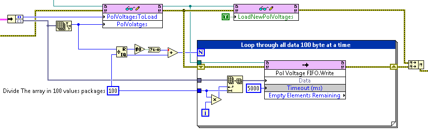
You're correct. It looks like I'm running out of memory. I have enough Block Memory, but it looks like it’s using LUTs instead, so yes by reducing the FIFO sizes it starts to compile. The error message I get is: “The Design requires more LUT as Memory cells…This design requires 19337 of such cell types but only 17400 compatible sites are available in the target device.†I just reduce the FIFO to the FPGA and that solved it. The problem was that I made the FIFO size to the FPGA too big, that design would make the SW easier just One Write on the RT, but now I need to do something like this in the RT:
-
Thanks, I'll see what I can do to follow your tips, if anybody else see something strange please let me know. //MIke
-
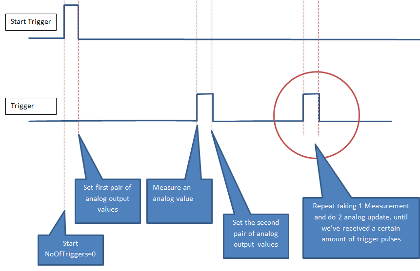
Hi FPGA expert. When I try “my way†of implementing a simple FPGA Analog Out VI, I run out of FPGA fabric (too may LUTs used). So what better way can I do this (if there is one), that don’t overuse my LUTs. My task is to: Make one analog measurement and control 2 analogue outputs that should be clocked out every time I get a digital trigger in. I’m running a sbRIO-9637 (Zynq7020) I’ve attached the simple application and I’m puzzled of what needs so many Look Up Tables (LUTs). Any suggestions? FPGATest.zip