Search the Community
Showing results for tags 'daqmx'.
Found 16 results
-
Hello there! I am using a PCI-6110 DAQ and the purpose is to synchronize a DO with some AO.something like this: Now, im using AO/StartTrigger to trigger a DO,however,this works fine on PXIe-6341(another card for test),but unable to work on PCI-6110 there is an error -200077 and it asks me to change sampTimingType from SampTime to OnDemand,obvious there is no such thing in DAQmx Timing VI. Finally I choose to use a Timing Node to set sampTimingType as OnDemand, and a new error -200452 come. Is there a way to solve this problem? By the way,this VI would run on a LV2012 computer ,so some newer function may not work. Here I post a example VI : example.vi
-
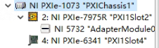
 I have a PXIe-7975R(FlexRIO FPGA with 5732 digitizer)and a PXIe-6341(DAQ) both installed in a PXIe-1073 chassis(you can check in screenshot below) and I want to synchronize there two device. my goal :The DAQ will output some control signal and the FPGA will acquire some other signal and they are synchronized . what I tried: 1. output a digital signal to 5732, however its DIO port somehow dont work,and that force me to input signal using AI port,but there are much much noise 2.this chassis used to run ScanImage( https://docs.scanimage.org/ an program based on MATLAB using DAQmx API),so Im sure the same thing could be realised using LabVIEW,however I couldnt find a way to do so. So ,is there a way to synchronize there two device?Or are there some modules like DAQmx avalible?(examples of 5732 only demonstrates Clock Select and Streaming)
-
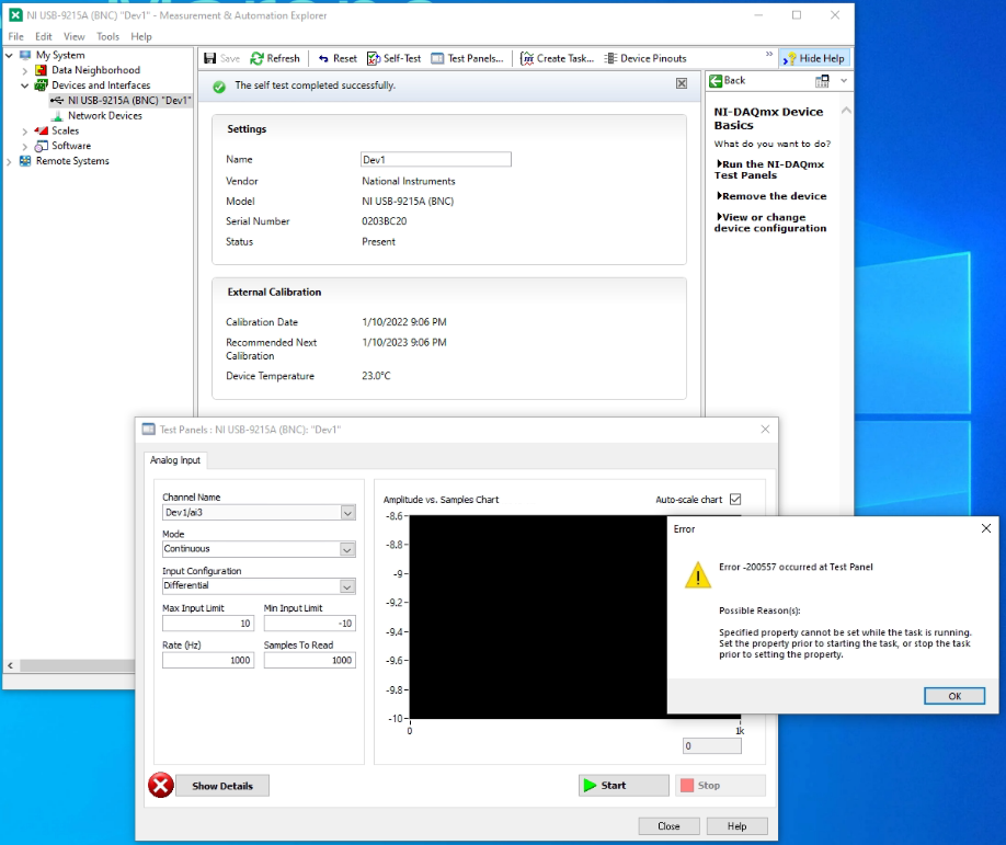
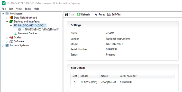
Hi all. After mounth of continuosly running with zero problem, now I'm getting the error "-200557 Specified property cannot be set while the task is running. Set the property prior to starting the task, or stop the task propr to setting the property". First I got the error on my program (basically, a QMH acquiring data from a DAQ module). But I get the same error from the MAX Test Panel of the module, even after many restart of the Windows PC and even after I uninstalled and installed again the DAQmx drivers and the LabVIEW runtime. This is the error and the MAX window. The module is a DAQ NI 9215 and is mounted in the cDAQ-9171 USB chassis. In other PCs where the same LabVIEW program is running, with the same combination of hardware (9171 + 9215) the typical MAX device list is like that: with the chassis 9171 listed and the 9215 is listed as a board in the chassis. Unfortunally the PC and the boards are in a remote location and, at the moment, I'm not able to phisically unplug the usb chassis or change the board with a different one. Can somebody help me, suggesting something else I could try, having only a remote access to the Windows PC? Thank you, Marco.
-
 Hello respected members I am working on a battery charging and discharging project and i use a Matlab\Simulink based dll file in my VI and its run without error with NI PXIe 8840 device ans PXIe-6368 DAQ card . It works according to the requirements and the outputs are same as Matlab simulation. How can i give signal to amplifier to get voltage and current for battery charging to see the behavior of the model in real-time ? How to generate the file with signals and load in in amplifier HMI? If someone can give me a good procedure it will be very helpful for me. Thanks Abdul Qadeer
-
 Hello LAVA community, I use a USB 6215. With two TTL output signals, two different colored lasers are to be triggered. TTL 1 activates a blue laser. TTL 2 activates a green laser. This external device also outputs 2 analog signals that I can capture with the USB 6215. While the lasers are active, the analog signals output characteristic values. The two TTL signals should be output by the USB6215 as follows: Both TTLs should be active for 10 ms every 100 ms, one after the other with a 2 ms delay. So TTL1 active for 10 ms, then 2 ms delay then TTL 2 active for 10 ms. The times should be adhered to as precisely as possible. The two analog signals should be calculated during the time in which both TTL are active (i.e. over the 22ms). The analog signals are sampled at 1 kHz. The analog data acquisition via DAQmx is clear. I only have problems programming the timing of the digital triggers (TTL) accordingly. Does anyone have any idea how to start? Maybe someone has already programmed something similar? Thanks in advance Pete
 -
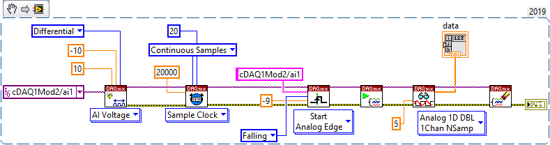
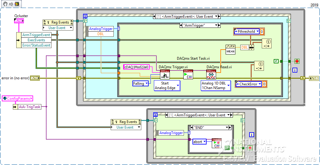
I have a requirement that I thought would be SIMPLE, but can't get it to work. I have a 9205 card in a little 9174 cDAQ USB chassis. My *intended* behavior is to wait (block) at the DAQmx Trigger/Start Analog Edge on, say channel ai1, until I get a falling edge thru, say, -0.050V. So I have a little vi (that contains 2 parallel loops) that I want to sit & wait for the trigger to be satisifed. I'm doing "routine" voltage measurements in another AI loop on a different channel. I want this vi to run separately from my "routine" voltage measurements because I want the app to respond "instantly" to input voltage exceeding a limit to prevent expensive damage to load cells. I was afraid that if I used either Finite or Continuous sampling to "catch" an excessive voltage, I might miss it while I'm doing something else. Yes, yes, a cRIO real-time setup would be better for this, but this is a very cost-sensitive task... I just want to "Arm & Forget" this process until it gets triggered, whereupon it fires an event at me. SO... I'm also reading the same voltage on channel ai0 for regular-ole voltage measurements, and just jumpering them together. I did this because I read somewhere that you can't use the same channel for multiple DAQ tasks - I *thought* I would need to set up the tasks differently. {but now that think about it, the setups can be the same...}. I've set up the DAQmx task the same as shipping examples and lots of posts I've seen. I'm supplying a nice clean DC voltage to a 9205 card using a high quality HP variable power supply. Using NI-MAX, I've verified that my 9174 chassis & 9205 are working properly. THE PROBLEM - When I run it, the vi just sails right through to the end, with no error, and an empty data array out. No matter WHAT crazy voltage I give the "DAQmx Trigger.vi" (set up for Start Analog Edge), it never waits for the trigger to be satisfied, just breezes on through as if it weren't there. If I set the Sample Clock for "Finite Samples", the DAQmx Read fails with timeout - makes sense, since the trigger wasn't satisfied. What could I possibly be doing wrong with such a simple task??????? So my fundamental misunderstanding still vexes me - does the DAQmx Trigger vi not block and wait for the trigger condition to be satisfied, like the instructions state - "Configures the task to start acquiring or generating samples when an analog signal crosses the level you specify"? I stripped my requirement down to the bare essentials - see the 1st snippet, the 2nd is my actual vi. Any ideas, anybody?
-
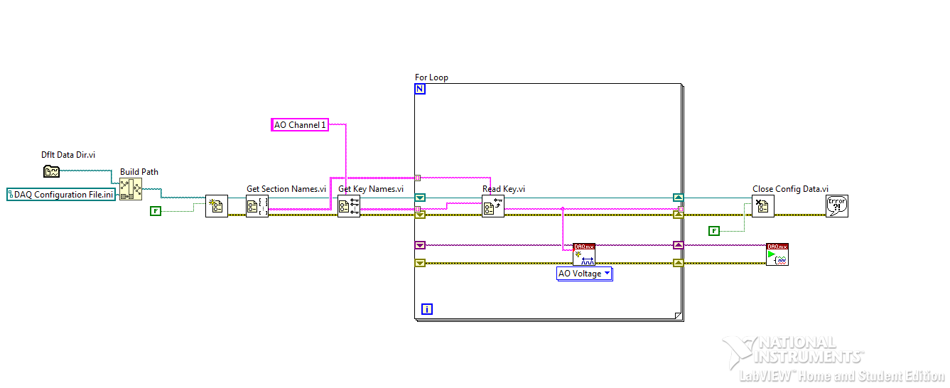
 Dear All, I'm new to this forum and I'm really glad I became a member. I am currently in the phase of designing a simple program which can control all the DAQmx channels using a configuration file (.ini) which is capable of change voltage range during mid-simulation. At the moment my .ini file reads as follows: [AO Channel 1] Name = T2 Physical Channel = cDAQ1Mod1/ao0 Max Value = 10 Min Value = 0 [AO Channel 2] Name = T3 Physical Channel = cDAQ1Mod1/ao1 Max Value = 10 Min Value = 0 [AO Channel 1] Name = T2 Physical Channel = cDAQ1Mod1/ao0 Max Value = 5 Min Value = 0 [AO Channel 2] Name = T3 Physical Channel = cDAQ1Mod1/ao1 Max Value = 10 Min Value = 0 My LabVIEW VI for the .ini script is attached. I'm relatively new to using configuration file functions and I don't really understand where "Get Key Names" section should be wired to. I have placed a constant on it for now which reads the "AO Channel 1" but how can I get it to read all the channels in the .ini file. I am welcome to all suggestions here, I just want to make sure that I don't cause any problems to any of the channels and use best practice methods. All constructive criticism welcome! Thank you. Read Configuration (INI) File (1).vi
-
Hello all, My question is: what is your preferred non-volatile way of storing daqmx task configurations? Backstory: For a long time I've used ini files to maintain task configurations between executions of a program. This has worked for primarily static DAQmx configurations but I'm looking at creating a test executive with some degree of flexibility, which means daqmx task configurations start to get more complicated. If you use MAX for storing your tasks: Do you run into problems accessing and maintaining these tasks even though you don't have direct access to the file? Or is there an unlisted storage location for these files? If you use ini/text based files: How do you keep things orderly? I'm running into all kinds of limitations with the format. If you use XML: Where did you find your schema? Did you write it? I know NI saves tasks as XML files, and so therefore the schema exists, but I haven't been able to figure out how to use it. I've created a task in my project and then dug through the XML of the project to find the attached image. I believe this would be the ideal solution, but a little bit of digging in around NI.com (I know...) and google (actually useful) has resulted in no answers. I know there is an elegant answer to this question, I've just not found it yet. Thanks in advance for your comments. Cheers, Tim M
-
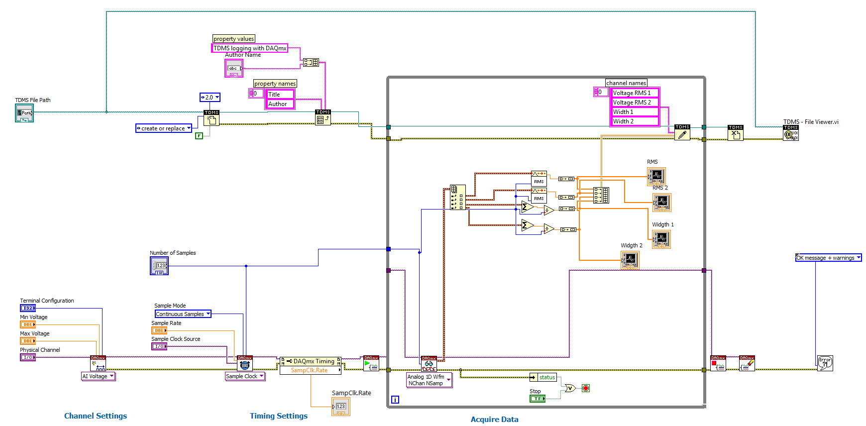
Hello, I'm using the 9229 and borrowed a community example to log 4 voltage inputs to TDMS. I need to output RMS voltage on channels 1&2 and the wavform on channels 3&4. Essentially what I've done is averaged channels 3&4 using the same # of samples that the RMS is averaged, that way I'm able to make sure they are time synchronized (see code attached). Another advantage doing averaging the samples is that I am reducing the amount of data to analyze later. When i compare the TDMS read results to the # of samples in the TDMS file there seems to be a discrepancy in time. I tried to add a time stamp to the logged TDMS file but couldn't get it to work. besides using time stamps, Is there an easy way to confirm that I am saving all of the data I am capturing? Eventually i will be logging data at 30min-40min intervals so I want to make sure that i'm not losing data. TDMS_Logging_Simple_4chan.vi
-
 Lets pretend I wanted to simulate a solar panel using a cDAQ, a programmable power supply and a light sensor. Id have to measure the voltage from the light sensor and the PSUs current, use those values to find the respective operating point on my light/voltage/current-curve and update the PSUs settings. Lets also say I wanted to do this for multiple systems in parallel, all connected to 1 analog input and 1 analog output module in 1 cDAQ. What would be the best way to achieve the quickest response time? Simply reading and writing single samples seams to be pretty slow (though I can encapsulate everything neatly this way). Is there a better way?
 -
I am trying to implement a simple DAQ Watchdog with single digital output but cannot find any logical way to reset the Watchdog timeout signal. One of obvious solutions is invoking DAQmx Reset Device.vi. Unfortunately, it does not work. The Watchdog goes to timeout state but the physical output signal does not turn to High. For some obscure reason (typical non-qualified guess:) I added bottom part of the code that is red-framed in the BD. The only difference between functional and non-functional code is using DAQmx Start Task.vi, that is located in “Solutionâ€-driven case structure. If Boolean control “Solution†is True, the code works; if False, it doesn’t. Please help to understand why launching conventional Digital Output task is necessary for normal functioning of the Watchdog? PS: Attempts to use clear expiration command instead of DAQmx Reset Device.vi were not successful. PSS: HW is PXIe-6358 PSSS: Unfortunately, I cannot post any image here. Any image format results in "You are not allowed to use that image extension on this community" . The VI is attached. watchdogTest150817.vi
-
Hello, I have created a vi that controls multiple writes (individually) by a switch. I have it so one individual switch controls one individual write (And is linked to individual clear, stop, error daqmx blocks). I do not think this is efficient as it takes about 4-6 seconds for the switch to actually write (True or False). So, I was wondering if someone could help me make my code more efficient so it would run a bit faster. Thank you Digital Outs fine.vi
-
Hello, I've been struggling with this problem for months now... I want to use a cDAQ9171+NI-9234 with an Advantech PC (AIMB-580). I have 3 computers like this and all with the same problem. I plug the USB cDAQ-9171, Windows detect the device and loads the proper driver (cDAQ-9171), it is displayed in MAX but self-test or reset always fails with error. At the same time, NI Devive Loader service hangs up. If I try to restart or stop this service it cannot complete the operation, the only way to finish this operation is to unplug the usb cable from the PC, then the service restarts correctly. Additionally the windows' event logger shows the next error message: or In one PC I re-installed Windows, installed DAQmx 14 and the problem was still there, this is with a Windows fresh-install... After this, I removed DAQmx 14 and installed DAQmx 9.8 (supplied in CD) and the it worked!!! I upgraded to DAQmx 9.9 and it was still working, so I stoped there as it was all I needed (9.8 has some bugs with NI-9234 that 9.9 solves). One thing to note, when it works, Windows first install cDAQ-9171 driver, but then inmediatly it changes to USB flash firmware updater, after this it returns again to load cDAQ-9171 and detects the NI-9134. When it don't work it only installs the cDAQ-9171 and doesn't load anything more... I tried in a second PC to repeat the process, but I have been not able to repeat the success, only the fail... I get the same error every time I plug the USB and I have not idea of what else try... I have disabled UAC, cleared the MAX data, reinstall windows 2 times, tried with DAQmx 9.8, 9.9 and 14. Forced USB flash firmware updater as Windows driver, changed BIOS settings (disable hyper-threading, VT extensions, USB legacy, etc.). I am almost sure that it is some kind of weird incompatibility or similar, the thing is that NI device loader always hangs-up. In the next days I'm going to try to copy the same exact configuration of BIOS from the working PC, just to be sure. Any recommendation?
-
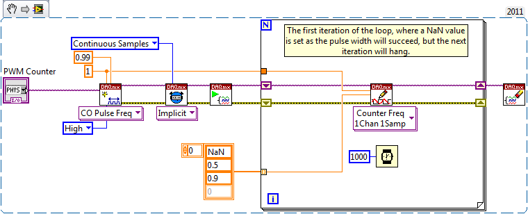
 This one caused me a day of grief. Turns out an error in the start up logic of one of my applications would request a duty cycle of NaN to a counter output I'm using for pulse width modulation. The problem is the NaN request goes through without returning an error. But the next request to update the duty cycle hangs the DAQmx write VI. After hanging, there's no way out, aborting the calling VI leaves LabVIEW in a sorry state. Example: WARNING: Running the snippet above can leave LabVIEW in an undefined state. Save your work before you do so! Now obviously a NaN duty cycle makes no sense, but I'd expect DAQmx to be able to handle such requests gracefully, either by ignoring them, or preferably issuing an error. I've observed this behavior on the USB-6343 device.
-
Hi LAVA, I need some help. I have a motor that moves a tray. During the movement of the tray, 2 switches will change value. I want to read out the counter value / motor position when the signal of the switches changes. (rising and falling edges) At this moment the only thing I can think off is a loop vi that reads the value of the swicthes and motorposition and evaluate the swicth states... But i'd rather have the position reading triggered by the digital lines. I'm running LV2010SP1, DAQmx 9.4 Hardware: cDAQ chassis: 9178 NI 9401 module => encoder signals are connected to this one. NI 9403 module=> 2 digital inputs(so the switches) are connected here. Thanks in advance for your help. Best regards, Wim
-
I would like to programmatically change the alias of a couple DAQmx devices to make a program more versatile. I have found an example at ni.com that will do this; however, it is in version 8.6 and I have 8.5. Could someone please visit that page and save a screenshot? https://decibel.ni.c.../docs/DOC-15998 Thanks.

.png.fa462cc4f9878b61da8b48b148f8187d.png)
.png.ee521e60e69dcdbb2a06e0a24319b8c2.png)