MarkCG
-
Posts
147 -
Joined
-
Last visited
-
Days Won
17
Content Type
Profiles
Forums
Downloads
Gallery
Everything posted by MarkCG
-
All I/O goes through the FPGA, and you can program a cRIO with both a program running on cRIO real time processor and one on the FPGA (also called a "personality") . You do not however HAVE to explicitly program the FPGA. You can use the "scan engine" if all you want to do is read and write I/O at a rate up to 500 Hz or so. All your program logic can be done in a LabVIEW program running on the real time processor. Where the FPGA comes in is when you need to do things at high speed, or with very high timing precision . For example, you want multiple PID loop controllers that run at 10 kHz, reading an analog input as the process data and outputting the control signal on an analog output or as PWM signal. You can do this on the FPGA-- you wouldn't be that fast otherwise. That or doing things like responding to digital triggers to perform some action within microseconds, things that generally require you to access I/Os on the in microseconds. You can also use the FPGA built in digital signal processors to do things like fourier transforms of data coming in and a whole myriad of other signal processing things that's contained in the Xilinx IP that you can access on some cRIOs. You are more limited in the datatypes and functions you can use on the FPGA-- typically you do things in LabVIEW fpga code you would not do in normal LabVIEW. On the real-time side of the cRIO, you can do pretty much anything you do on a normal computer with far fewer limitations-- you have access to the internet, serial communication to instruments, all the various math and analysis VIs, pretty much anything except UI related things (unless you have cRIO with a display port) The host is generally just the thing you use as a user interface. PC, tablet, phone, what have you. Typically the cRIO has the machine's logic built into its real time program, and the "host" sends commands or makes requests of it to do something via TCP/IP, network streams, or even UDP. The cRIO handles those requests and then lets the host know whether it can do them and whether it did or not.
-
 update to this thread: we got it working on the cRIO 9068. See this thread https://sourceforge.net/p/labview-zmq/discussion/general/thread/87780372ed/ for details. Thanks to everyone here and Martijn Jasperse for all your help.
- 72 replies
-
- 2
-

-
- networkcommunications
- datasocket
- (and 1 more)
-
thank you Rolf and SmithD, this helps. I think he is making some progress now by compiling on the cRIO although it's not working yet. I've informed him of this thread and will update if we can get it working!
- 72 replies
-
- 1
-

-
- networkcommunications
- datasocket
- (and 1 more)
-
Turns out one of my coworkers is trying to compile zeromq for the cRIO-9068, but not having success. Anyone ideas or have the .so file available? We also have a cRIO-9038 which is a different processor architecture, maybe it will work there?
-
I was going to say beckhoff as well. I'm a big fan of the beckhoff "EtherCAT Box" series. https://www.beckhoff.com/english.asp?ethercat/ethercat_terminals_accessories_overview.htm . Very reasonably priced too and you can get rid of enclosures.
-
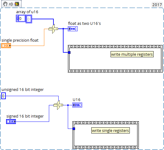
What is the datatype you want to write? If the manual for the device say that a particular register is interpreted as a 16- bit signed integer (I16 ) you will need to use the type-cast function on the I16 data in your LabVIEW program and wire that that to the write single register VI. For single precision floating point values, which are 32 bits, the modbus device will typically have you write to two consecutive registers in memory, typically called the high word and low word. It's done this way because every modbus register is 16 bits. So what you do is this and wire the array of U16s to the "write multiple registers" VI. Usually if the high word precedes the low word in memory this will work. If not the you have shuffle the high and low word. Modbus is fairly old, dating back to the 70's and doesn't have built in support for flaoting point.

-
Unfortunately you probably have to make a voltage divider but the Winford enginering terminal blocks are pretty useful for this because you can solder in your divider resistors and then connect the block to the module with a d-sub cable https://www.winford.com/products/brkdd37mf.php
-
Modbus RTU message framing
MarkCG replied to drjdpowell's topic in Remote Control, Monitoring and the Internet
Fair enough. I will say that the old library did the job pretty well though, never had a problem with it, even running on something as old as a fieldpoint. I actually modified to make it faster on reads as well, and also to make communications library for a flowmeter that used a proprietary bastardized version of modbus. The core logic of it is pretty solid and worth looking at. -
Modbus RTU message framing
MarkCG replied to drjdpowell's topic in Remote Control, Monitoring and the Internet
Just curious, but why bother when there are multiple native LabVIEW implementations already? There was the "original" NI library , the LVOOP NI implementation, and I believe at least one third party implementation. -
Will statecharts survive to move to nxg?
MarkCG replied to Taylorh140's topic in Application Design & Architecture
I actually think it has survived in a certain form--- it looks like statecharts are used in programming the new functional safety cRIO modules http://www.ni.com/white-paper/53844/en/ -
Do you guys think that sending the automated error report to NI after a hard crash actually helps them fix things ? I usually click no out of instinct but may be I should start. It's hard to believe how much we put up with LV's hard crashes-- for me a couple a day is no big deal. But otherwise they seem pretty rare in other programs nowadays. Chalk it up to the crustiness of the codebase I guess.
-
I've been experiencing a lot of crashes with 2017, way more than with 2014 which is what I was using before. Why or how they are caused I can't say.
-
The DSC toolkit Glyph really are pretty horrible. More 1995 than 2002 if anything. I've been using Edraw max to create graphics. There is a lot of P&ID stuff in there. No high vacuum but it's pretty easy to create graphics from the raw shapes and apply color gradients to give it that 3D effect. The ability to scale easily because of vector graphics is awesome too. You can set you drawing sizes in pixels directly which make it really easy to design for a given resolution. https://www.edrawsoft.com/pid-examples.php I will typically make a P&ID with edraw, export it as a PNG, drop that directly in the front panel and then drop my customized controls with graphics also made in Edraw in place over that. It's produced pretty decent results.
-
Do running VIs with a closed front panel use CPU for UI elements?
MarkCG replied to MarkCG's topic in LabVIEW General
thank you, I am trying to get some more insight into what happens under the hood. I have noticed some cpu spiking behavior when switching between tabs of a tab control on a cRIO embedded UI which actually caused a scan engine timed loop to miss. Not important as far as the application was concerned but it got me me thinking on how to exert more control on what the UI is doing. -
Full DataGridView for LabVIEW - OPEN SOURCE project underway
MarkCG replied to Mike King's topic in User Interface
DataGridView.lvclass:Set Cell Enabled State.vi . You have to iterate over the cells to disable the columns you want. Now as far as setting individual cell values programmatically without restarting / redrawing the whole table, does anyone have an idea? Nothing seem obvious -
Say you have several VIs that you are inserting into a subpanel display as pages, as an alternative to making them pages of a tab control. Say those pages each have I don't know something that requires more than average CPU to draw like an X-Control that's getting updated a decent rate. Does LabVIEW use resources to redraw each of those diplay elements if the front panel is closed in this situation?
-
Full DataGridView for LabVIEW - OPEN SOURCE project underway
MarkCG replied to Mike King's topic in User Interface
Very nice Mike, I am going to make use of this, it looks so much better than anything you could possibly do with arrays of clusters. Is there a way to prevent a column from being edited by the user? -
What fields of maths are most beneficial to LabVIEW programmers?
MarkCG replied to TheStrangeQuark's topic in LabVIEW General
probably not graph theory. I highly, highly, highly recommend recommend DSP for scientists and engineers by Steven W. Smith http://www.dspguide.com/pdfbook.htm if you are working with LabVIEW there is probably something in there relevant to what you are doing. -
Does any one have any experience dealing with ethercat slave connection and disconnection while the system is running? Say you have a daisy chain of etherCAT slaves and the last one gets disconnected. From what I have seen the Scan Engine stops and goes to configuration mode. What if I want the system to just keep running as normal?
-
This is why i like the cRIOs and cDAQs with the display port. Self contained system that the IT guys don't really even recognize as a computer.
-
It would be cool if LabVIEW could gain some ground in the embedded world, instead of becoming more and more a high performance high cost niche. I think Python support is the right move. There are plenty of other DAQ manufacturers out there that support it and NI would lose out if they didn't. I'm learning python and am pretty impressed with how easy it is to get back to text programming with it after many years of LabVIEW. Text programming has come a long way from the days of the DOS based IDEs and C++ I learned back in high school.
-
Thank you Rolf! As always you provide great information. Sounds like all those options will cost far more in development time than buying the hardware. I'll just have to get the Profibus module then.
-
Hi all, I would like to communicate to PROFIBUS DP device with a CompactRIO 9035. I did some research and I am not happy about my options. The cRIO module to talk to it is $1500 which seems outrageously expensive for what I want to do, which is talk to a single device at a 9600 baud. It also looks like you need to use it in FPGA mode, which will force me to have to start compiling bitfiles for my nice scan engine only project. It does look like PROFIBUS DP uses an RS-485 physical layer which is good. Theoretically I could just communicate to the device with my built in RS-485 port. However, I am not finding any PROFIBUS libraries available for download that work with a generic serial port. I believe the NI-PROFINET driver is tightly integrated to the cRIO profinet module. I am also not jazzed about implementing a PROFIBUS protocol from scratch. Does anyone have suggestions on good 3rd party adaptors or libraries that would allow me to communicate to this PROFIBUS device with a minimum of programming?
-
I wouldn't bother. You would have to reverse-engineer how DAQmx communicates to that device and then implement that yourself. Explain to them how much of your time this would take and what it would cost at your hourly rate vs buying the module
-
Just spitballing here: maybe you could measure directly the electrical resistance with the 4-wire method of the part and correlate that to temperature using the temperature coefficient of resistance. Using a sine wave current at a particular frequency you can use a lock in amplifier which can detect small signals in where there is a lot of noise. I am assuming the part is metallic and conductive. You are putting TCs on it so you can get leads on it I assume. The other thing about using that technique is you can extract other information: the specific heat capacity of the part as a function of temperature. That all falls under the technique known as "modulation calorimetry" . Using TCs simultaneously would allow you to know the start and end temperatures accurately, with the high speed resistance measurement filling in the gaps in data.