Search the Community
Showing results for tags 'design'.
Found 19 results
-
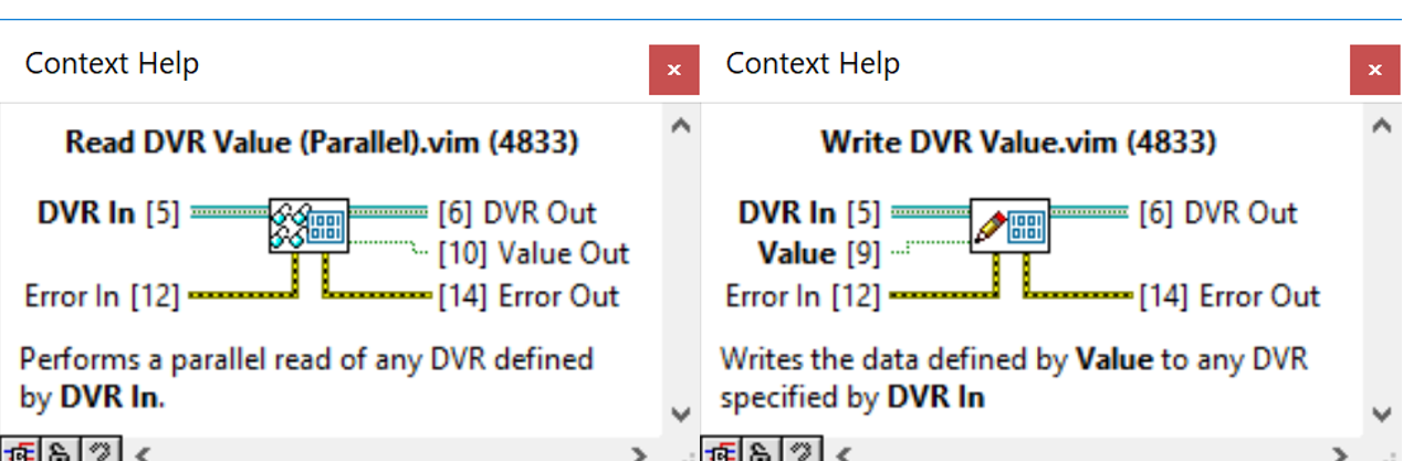
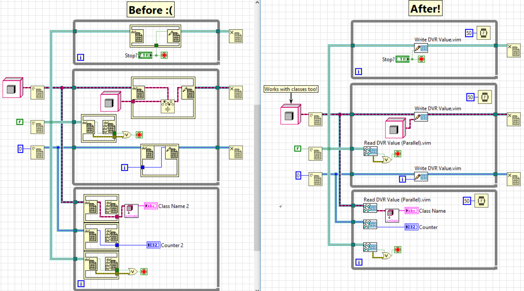
 The introduction of parallel, read-only access for DVRs in LabVIEW 2017 adds a great deal of flexibility to using DVRs to monitor values in parallel executions of code. Fo\The downside of this, of course, is the necessity of using the In Place Element (IPE) throughout your code simply to read the value. Having IPEs throughout your code just to read a value both takes up block diagram real estate and also takes more clicks than desirable to insert. Similarly, though less frequently, there are times when you only need to update the value within a DVR without actually performing any logic inside of the IPE. This situation is less frequent, at least for me, as I am usually using arrays or classes with DVRs such that I actually need to modify the existing data rather than simply replacing it. A more preferable solution to the above situations would be to have Read/Get and Write/Set VIs for the DVRs to simplify the process of working with them. This way, and IPE on the block diagram would only be needed when you were actually modifying the existing data within the DVR, rather than simply overwriting or returning the current value. Thanks to the power of malleable VIs and the type specialization structure that is now officially released in LabVIEW 2018, a better solution is now available. I’ve created two malleable VIs, Read DVR Value (Parallel) and Write DVR Value that allow you to perform a write and a parallel read on any DVR data type. Now, you can use a single VI that you can insert via Quick Drop to read or to write DVR values. Download the attached ZIP file to access the two malleable VIs and example code, and please let me know your thoughts in the comments! DVR Read and Write VIs 1.0.0.zip
-
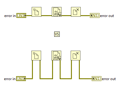
Hello All, First time LAVA poster here with my first question. Why do some LabVIEW programmers insist on wiring the error cluster to the bottom of their VI as opposed to the sides as shown in most NI documentation. Is there any benefit to it? Is it 100% a preference thing? Is there a way to make LabVIEW connect error wires like this automatically? I've only seen it in advanced LabVIEW code from experienced programmers and some parts of the Actor Framework. Your insight and experience is appreciated!
-
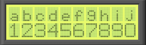
View File LCD panel.ctl, LCD panel.vi I've been playing around with making some controls that mimic popular electronic components and here is one of them. It's a basic 10 x 2 character LCD panel. You can play with the colors to create a variety looks. You could also imagine modifications to create animated LCD panels. Feel free to incorporate into what ever you're creating. Submitter tylertroy Submitted 08/17/2016 Category User Interface LabVIEW Version
-
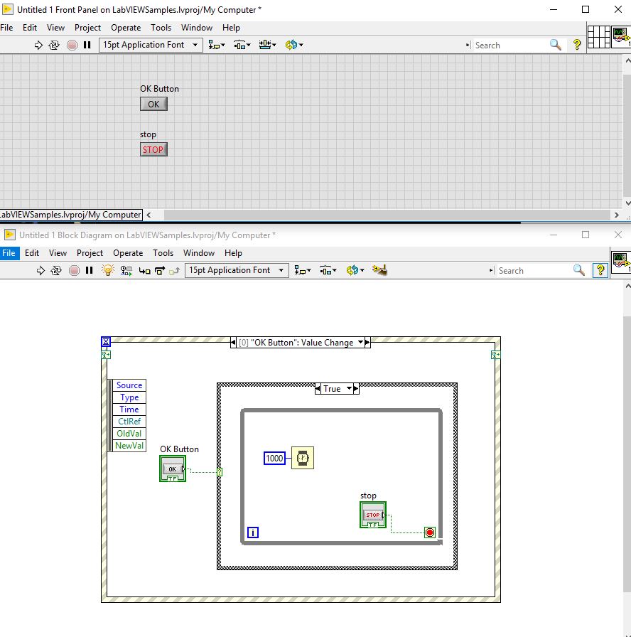
 Hi I have a simple program which has only 2 buttons for the user interface. When the user clicks OK I want the program to get into the event structure case called "OK Button". Once it is inside there is a loop which continuously waits for 1 second until "Stop Button" is called from the user. But because once the user presses the "OK Button" the program gets into the event and therefore I can not call the "Stop Button". Is there a way to call the "Stop Button" even if the program is inside the event ? Thanks event_out.vi
-
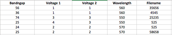
Hello Labview Users, I happen to have thousands of csv data file that I work with. The only way I recognize them is putting their characteristics in the file name. Which brings the problem of making the names too long and Microsoft doesn't like to accept long name. So I wanted to build a database for all my files. I am in the preliminary stage of building it ( I have attached the file and some of you may have seen it before). What I want to do is, have all my files in the database with random names and list them based on their characteristics. I want to do that in my application in the place of 'file' box. So that I can click on the file and run it (double-click on the file in application to make them work in active file). based on the parameters listed on the database I want to filter them to find any specific file. How the interface of database should look like is shown blow (Image) . It doesn't have to be a real database, just a directory application. I am trying to make it without the database toolkit. If anyone can help me out and guide me out or guide me in the right direction then that would be great. Thanks. Multicolumn list box v1.5.vi
-
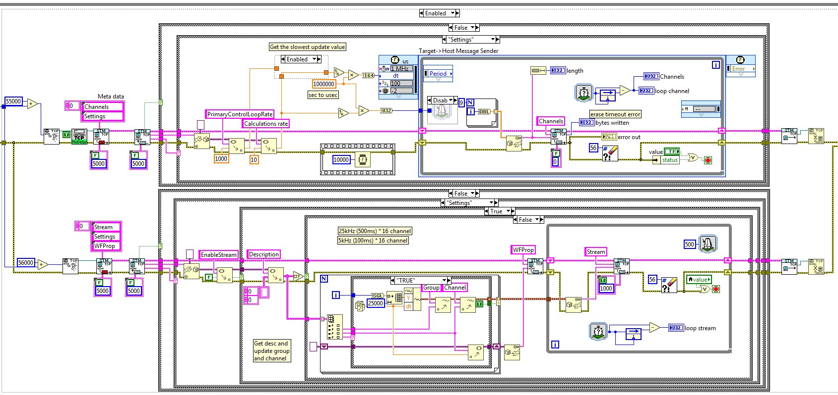
Hi everybody, I'm actually running on a problem with a TCP connection between 2 cRIOS. One cRIO is a server which writes 76 bytes long messages every 10ms (today, but can be anything between 1ms and 1s) using STM Write VI (so at the end it pushes 82 bytes long message in the TCP write function). I want that message to be sent only if the client as time to read it, so I set the timeout to 0. The other cRIO is a the client with tries to read on the TCP link at a speed of 1000Hz (1ms, Wait next Multiple used to ensure that the loop is not running faster). I use the STM Read VI to get the data sent from the other cRIO. The read function has a timeout of 100ms. What I was expected is that the client loop would actually runs at 10ms rate (server writing rate) due to the 100ms timeout. And if the server writes faster, it would follow the server rate. If the server rate is greater that 100ms, error 56 would be fired, and I would handle it. What happens is that the server writes the 82 bytes every 10ms. But the client loop is always getting data and runs at 1ms ; which means that the timeout is not respected ! I disabled Nagel algorithm on the server side to be sure that the message is sent when requested, but it didn't help. The client acts like there is always data in the read buffer. Even if it can be right for the first iterations, I would expect that running at 1ms rate, the client would empty the buffer rapidly, but it seems that it never ends... Moreover, the longer the server writes, the longer it takes for the client to see empty buffer (timeout reached again and error 56) when the server is stopped (but connection not closed). Does somebody already ran into this issue ? Any idea on how I can solve this ? Server code is attached to the post. 2 TCP connections are established between the server and client (so same IP address, but different ports), but only one is used (upper loop). The other opens and close immediately because EnableStream boolean is always false.
-
 Hello again LAVAG, I'm currently feeling the pain of propagating changes to multiple, slightly different configuration files, and am searching for a way to make things a bit more palatable. To give some background, my application is configuration driven in that it exists to control a machine which has many subsystems, each of which can be configured in different ways to produce different results. Some of these subsystems include: DAQ, Actuator Control, Safety Limit Monitoring, CAN communication, and Calculation/Calibration. The current configuration scheme is that I have one main configuration file, and several sub-system configuration files. The main file is essentially an array of classes flattened to binary, while the sub-system files are human readable (INI) files that can be loaded/saved from the main file editor UI. It is important to note that this scheme is not dynamic; or to put it another way, the main file does not update automatically from the sub-files, so any changes to sub-files must be manually reloaded in the main file editor UI. The problem in this comes from the fact that we periodically update calibration values in one sub-config file, and we maintain safety limits for each DUT (device under test) in another sub-file. This means that we have many configurations, all of which must me updated when a calibration changes. I am currently brainstorming ways to ease this burden, while making sure that the latest calibration values get propagated to each configuration, and was hoping that someone on LAVAG had experience with this type of calibration management. My current idea has several steps: Rework the main configuration file to be human readable. Store file paths to sub-files in the main file instead of storing the sub-file data. Load the sub-file data when the main file is loaded. Develop a set of default sub-files which contain basic configurations and calibration data. Set up the main file loading routine to pull from the default sub-files unless a unique sub-file is not specified. Store only the parameters that differ from the default values in the unique subfile. Load the default values first, then overwrite only the unique values. This would work similarly to the way that LabVIEW.ini works. If you do not specify a key, LabVIEW uses its internal default. This has two advantages: Allows calibration and other base configuration changes to easily propagate through to other configs. Allows the user to quickly identify configuration differences. Steps 4 and 5 are really the crux of making life easier, since they allow global changes to all configurations. One thing to note here is that these configurations are stored in an SVN repository to allow versioning and recovery if something breaks. So my questions to LAVAG are: Has anyone ever encountered a need to propagate configuration changes like this? How did you handle it? Does the proposal above seem feasible? What gotchas have I missed that will make my life miserable in the future? Thanks in advance everyone! Drew
 -
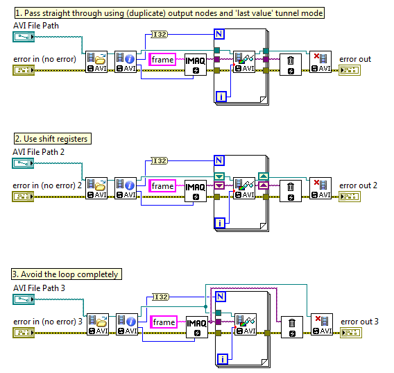
 I'm aware of this thread on passing errors around loops. https://forums.ni.com/t5/LabVIEW/Error-in-out-in-shift-register-yes-or-no/td-p/1077703 On a similar note, what is deemed the best way to handle wires containing references to devices or sessions in a loop? What are the pros and cons to consider? I've made a few examples using the Vision AVI2 library, but the same thing could apply to an IMAQ camera session, or indeed a TCP/IP or serial communication session, where you need to initialize a session, do your core logic (the loop) and then shut it all down at the end. In my case I already have the error cluster managing the function order execution. With that in mind, what's the best way to set up my wiring? Using LabVIEW 2016, 64bit. refnum_wiring_style.vi
-
Can I create a VI using just C code? I have a C code which has some complex function with inputs suppose x, y and outputs p and q. I want to know whether we can create a VI (with/without VI scripting) from whose control panel, we can control the inputs x,y and be able to see the outputs p and q without bothering about the function(which is included in the C code). I don't want to use importing .dll files(which many may suggest), instead create labview blocks/objects on the block diagram of the VI file. Please throw some light on how to do if it's possible. Thanks in advance.
-
Version 1.0.0
1,921 downloads
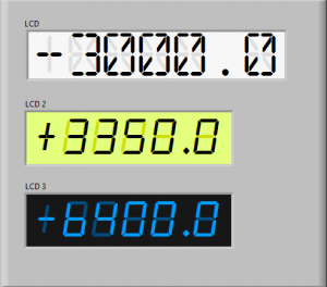
Here are a couple of controls that simulate an LCD numerical display. You will need to install the fonts for them to work as pictured. You can achieve the same things with which ever font you like but it really only works with mono-spaced fonts. You can customize each control in the "Advanced" right click menu of the control to set the precision you need or to modify the font size. Note that you can't change the font size without customizing the "background" label font too. Accessing and modifying each component is most easily achieved by changing the z-order of the components using the Ctrl-K, Ctrl+J shortcuts while in tweezer mode -
View File LCD1.ctl, LCD2.ctl, LCD3.ctl Here are a couple of controls that simulate an LCD numerical display. You will need to install the fonts for them to work as pictured. You can achieve the same things with which ever font you like but it really only works with mono-spaced fonts. You can customize each control in the "Advanced" right click menu of the control to set the precision you need or to modify the font size. Note that you can't change the font size without customizing the "background" label font too. Accessing and modifying each component is most easily achieved by changing the z-order of the components using the Ctrl-K, Ctrl+J shortcuts while in tweezer mode Submitter tylertroy Submitted 08/17/2016 Category User Interface LabVIEW Version alarm_clock.zip digital-dream.zip
-
Version 1.0.0
915 downloads
I've been playing around with making some controls that mimic popular electronic components and here is one of them. It's a basic 10 x 2 character LCD panel. You can play with the colors to create a variety looks. You could also imagine modifications to create animated LCD panels. Feel free to incorporate into what ever you're creating. -
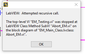
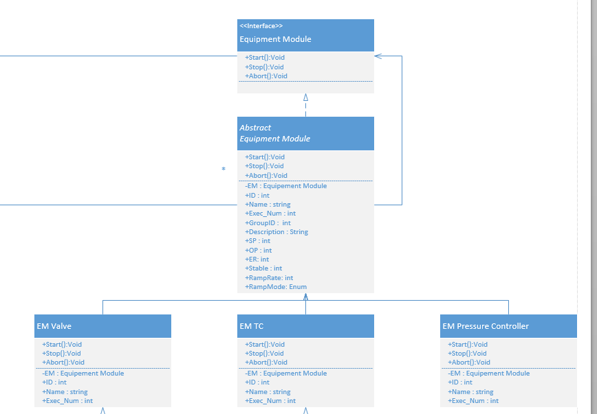
 So this will seem fairly long winded but I believe some people here will find this to be an interesting question and hopefully people can point me in the right direction. To give you guys some background I am a process control integrator working with PLC's and CRIO's to create automated solutions for out clients. I have a background in Software engineering and have worked a great amount in the past in Object Oriented languages such as Java or C#. I have only been using LabVIEW for the past 2 years and this is the first time I have utilized the OO features of LabVIEW. One of the first things I looked into was if interfaces and abstract classes existed in the OO concepts for LabVIEW. I learned quickly they do not and after looking through the white paper I had a grasp as to why. Which is fine but it lead to the rest of what I am going to explain. The end goal is to create some Equipment control modules based on the S88 standard that is used in process control. Typically an EM would have a Start(),Stop(), and Abort() function. We would like to create a library of these EM’s and keep with an overall good structure using inheritance in a OO style. I can inherit information from a parent class, and I can override the functions from a parent class as well. What is giving me problems however is that I am encapsulating a parent class object in the child object data area and I am attempting to utilize an override function on this encapsulated object. Our reasoning for an encapsulated object is to allow for dynamic creation of new EM’s that can be utilized by a previously created EM. I would like to be able to abort a parent EM and have that abort any cascaded EM’s that are children of it. With my current setup that I would use in C# I am running into a recursion error. Picture should be attached. I believe I understand the reason for this error, which is that technically we are recursively creating these EM’s and therefore can have essentially an infinite amount in memory to interact with. This wraps into why I was wondering in the first place about interfaces and abstract classes. If my top Object was actually a interface instead of an actual class you would be able to declare it but it would not be instantiated until a constructor created the more lower down classes. This would get rid of this recursive error as I could check if the child EM is instantiated before I decided whether a function could be utilized on it. So my question to everyone is, is there a work around that would give me the same result or is there a more LabVIEW acceptable way to do this? Attached is my UML diagram, the error I am receiving, and the LabVIEW Project that I created to attempt to demonstrate the architecture I wanted. Thanks for any help! ClassOOTest.zip
-
hi i wanna control robatic arm in labview. i have the different parts in vrml and wanna add them together. but don't khow how to do that with NI_picture control/add object ... can anybody help me ? thanks
-
 I have to develop an application and I would like some help designing the architecture. The system controls a number of pumps and valves to create flow around a network of pipes. There are flow meters in the network which are used as feedback for PID to maintain a flow. The network of pipes is gradually opened up to get flow and then PID kicks in to maintain a flow. The test sequence is pretty much a big state machine. For example: 1. Open valve 1 2. Wait for pressure to build 3. Ensure temperature is not over limit 4. Etc I will have a number of different screens which I want to load into a main sub-panel: · Main SCADA screen (show state of all valves pumps etc) · Test setup screen (configure tests) · I/O screen · Alarm screen I will also have a number of I/O processes: Inputs · Digital (valve sates) · Analogue (flow meters, temperature etc) · Modbus and serial devices (flow meters) Outputs · Digital Output – Valves etc · Analogue - Proportional valves I want to use the Actor Framework because I’ve used it 3 times now and it is easy to spawn processes, make popups, inter-process messaging, error handling etc. I can have all my processes separate (high cohesion) with separate user interfaces (if they have a UI) . My problem is that AF and State machines don’t really go that well together (correct me if I’m wrong). What happens when I want to do PID or loop in the same state? Time delayed message? A a VI for each state and enqueue the next or same state from within that VI? Does anybody know a good way to incorporate a state machine into AF or should I chose a different way of doing things? Any thoughts will be appreciated. Cheer Lewis
 -
 Hi All, I have an application where I store the data in a cluster. Suppose this is my ver. 1 of the application and the cluster consists of 3 I32. and I ship this application to the customer. Now for the ver 2 I want to store a string to the cluster so I updated my cluster to 3 I32 and 1 String. But this ver 2 should also be able to read ver 1. just like MS Word 2007 is able to read .doc files In my design, I am stroing the version number and data(as variant) in a cluster and convert that cluster to variant and do a 'variant to flattened string' before saving it to a file. I am attaching my desing protoype here so you get a better idea of what I am talking about and suggest me if you think it can be done in a better way. Thanks, Ritesh ClusterVersionControl_Design.vi
 -
 Hi, I am trying to tabulate data into a form such that i can display data points from a signal into an array that ultimately can be displayed graphically in a restful web service. Iv'e been able to simulate data via a waveform indicator using a simple simulate signal vi, but i can't seem to find a solution anywhere that will allow me to extract and display points from a signal from within a simulation loop. I've tried using the indexer funtion which seems to be limited and using the collector funtion which I am struggling to get to grips with. If anyone could help me find a solution or give me advice on how to go about solving this problem I would appreciate it so much! Thanks, Christian controlloop.vi
 -
 Hello, I am new here. I am having a difficulty setting up a application. I have three vi's I am running to do some data acquisition, stage control and processing respectively. One of the vis is running on a 64bit labview platform. The other two are running on a 32bit platform. They all internally are statemachines, but I would like to design I way to activate certain states based on states from other vis. For example here is what I am trying to do, below is a diagram of the internal states and how I would like them to communicate: vi_A: 'Idle'->Do_SomethingA_1 -> Switch_vi_B_to_Do_Something_B_2 ->... vi_B: 'Idle'->Do_Something_B_1 -> Wait_for: Switch_vi_B_to_Do_Something_B_2 -> Do_Something_B_2 ->... vi_C: 'Idle'->Do_Something_C_1 -> ...
 -
 I know there is the windows message queue API that can be downloaded, and I have this working fine and am receiving messages. But unfortunately this requires polling the message queue in my application. I'd like to handle these messages as events in an event structure, and I can do that by having a polling loop to manage the message queue, which then fires a user event when the correct message is captured from windows. But, is there a way to do this any cleaner, similar to being able to register events based on callbacks?