Search the Community
Showing results for tags 'daq'.
Found 20 results
-
LAVA users, We are looking for alternatives for NI DAQ devices for industrial automation. Since NI has its devices mostly focused on advanced/high speed/high precison data acquisition/processing its prices are inadequate to simple automation tasks. I would also say that NI PC based daq systems are expensive if need to be distributed systems (found this but still relatively expensive cRIO required). Just now we need to extend our compactDAQ based system with two DIO modules. We even have free chassis slots for this, but station that needs this IOs is few meters away from PC. How easier would it be if we could use single ethernet cable.. Ofcourse we can add another small cDAQ (what we probably going to do) but this is slightly expensive solution for our customer. Does anyone have some experience with 3rd party solutions? Any known daq devices vendors? Standalone ethernet daq modules? Regards, Zyga
-
Hello Everyone, Need some verification with daq program. I have one force sensor that connectd with my usb daq device. with this force sensor, unknown object is connected(hanging) and i want to find the mass of this object (F=ma) so i am taking continous sample and generate waveform graph. After the scaling, my waveform will be in Newton unit. my question is: if i take RMS of this waveform(1d Array data point) and divide by g (9.8 m/s2) then whatever value come is my correct mass? (F=ma). Thank you in advance
-
hi i have a question in basic understanding of update rate sample rate samples per buffer and cycles per buffer. i have DAQ 6343 and electronic circuit. i'm using AO0 for generation sine wave at these frequencies 10Hz, 100Hz, 500Hz, 1kHz, 3kHz this signal enters to electronic circuit. and after conversion i must to measure two outputs of this circuit by AI2 and AI3. from my understanding of tech spec of the daq analog output update rate is 900kS/s and analog input update rate is 500kS/s as i understand if i have freq = 3kHz the maximum sample rate per buffer is 300 samples and if i have freq = 10Hz i can generate this signal with 90000 samples per buffer? for analog input the formula is the same? that meaning of cycles per buffer? which sample rate of AI i need to setup to measure data fast and accurately? thanks for answers
-
I am trying to implement a simple DAQ Watchdog with single digital output but cannot find any logical way to reset the Watchdog timeout signal. One of obvious solutions is invoking DAQmx Reset Device.vi. Unfortunately, it does not work. The Watchdog goes to timeout state but the physical output signal does not turn to High. For some obscure reason (typical non-qualified guess:) I added bottom part of the code that is red-framed in the BD. The only difference between functional and non-functional code is using DAQmx Start Task.vi, that is located in “Solutionâ€-driven case structure. If Boolean control “Solution†is True, the code works; if False, it doesn’t. Please help to understand why launching conventional Digital Output task is necessary for normal functioning of the Watchdog? PS: Attempts to use clear expiration command instead of DAQmx Reset Device.vi were not successful. PSS: HW is PXIe-6358 PSSS: Unfortunately, I cannot post any image here. Any image format results in "You are not allowed to use that image extension on this community" . The VI is attached. watchdogTest150817.vi
-
Hello, I have created a vi that controls multiple writes (individually) by a switch. I have it so one individual switch controls one individual write (And is linked to individual clear, stop, error daqmx blocks). I do not think this is efficient as it takes about 4-6 seconds for the switch to actually write (True or False). So, I was wondering if someone could help me make my code more efficient so it would run a bit faster. Thank you Digital Outs fine.vi
-
Hello, I think this topic is very important for everybody that are doing advanced DAQ. Because it you want to save an event, you need first to see it(real time analysis), and than to save the transition how the event happened(that means to have values, before the event happened). Using consumer producer structure. i'm trying to save data into some kind of buffer. my main goal is to delay values. I successfully created a delay using Delay values.vi, the problem is i think it makes the while loop slower. If anyone knows what is a good practice to create a delay for large amounts of samples 100k, 200k, 300k samples? Is a delay values.vi good practice, or is there another better way? Thank you
-
 Hi, Recently I have been trying to develop a set of classes for data aquisition (as the encapsulation makes other tasks easier) however I keep running into several issues (described below). I was wondering what you guys did for your OO DAQ systems. I've found a few presentations lying around on the net but their implementations do not seem to work when using DAQmx based measurements. I am trying to measure the inputs from two seperate instruments: (1) Torque Sensor (2) Encoder. Sometimes these instruments might be using a DAQmx analog input and other times a .DLL. My original thought was that I would have a parent class called Measurement with several functions (Initalize, Configure, Read Data, Close) that would be over-riden by its children Analog Input (DAQmx) and Digital Input (Seperate .DLL). There then would be (for example) an Analog Input object created called position and a digital Input object called torque. This seemed to look nice on paper, however it didnt work as my DAQs tasks need to be combined (you cant have several tasks on a single device.) As this didnt work, I approached it with a different setup. This time I had a parent class called Instrument that has two children Torque Sensor and Encoder. Again, things get tricky, as sometimes I might want to use an analog DAQmx task for both the Torque Sensor and Encoder. What is your typical OOP class structure like for DAQ? Thanks!
 -
I had to go to a customer for a very old project of theirs. They still use LV6.1 , tradiotional DAQ , ... After reboot of the PC and login by another user all configured DAQ tasks were gone. There is no documentation on the setup so recreating is not an option. They have an old image of the PC so .... where does MAX (version 2.2) store it's DAQ tasks, scales etc ? Thanks Wim
-
Hello everybody, I am trying to create a DAQ VI for Fluke 2638A that measures temperature every 15 minutes. I created a producer/consumer architecture for this VI. During the 15 minute interval (900s), how can I have the Stop button end the program? I need interrupt the Wait for Scan Complete subVI since this is where it stays during the interval of 15 minutes. I am thinking of adding a shared variable node where the subVI is able to read the value but I am unsure of this approach. Please let me know if there are better ways to do this VI or any comments that I can learn from. Thank you. Fluke_VI_Rev2.vi
-
Hello Everyone: I am doing lightsheet imaging. I scan the sample with the sheet of light. I trigger the camera and derive Galvo through DAQ. The staircase.with.external.trigger.vi is the code for triggering and writing the voltage. MY camera is Thorlabs USB ccd camera. I attached all the available code I have it for the camera. I would like to integrate the camera and DAQ code in one program which I can save one image during the scan.( During the scan I see several stripe of light in camera, I want to save all stripe in a single Image or capture all of them in one exposure time.) Any help or advise is appreciated. Please don't hesitate to ask me if you have further information. Thanks in advance. Camera.code.zip staircase.with.external.trigger.vi
-
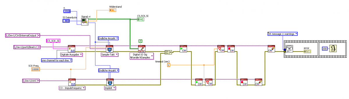
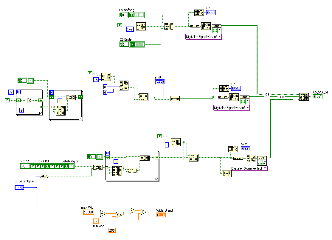
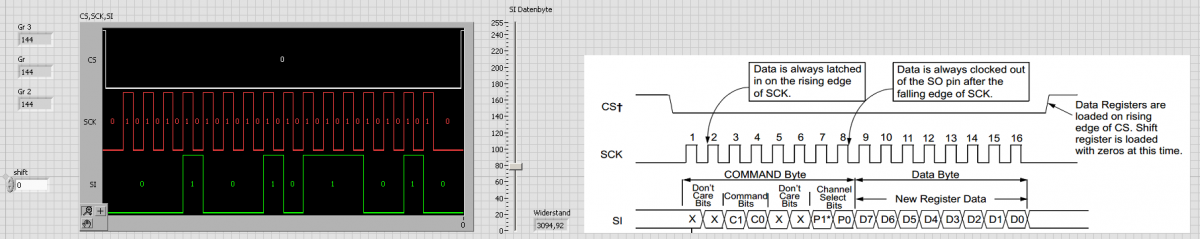
hello, I try with the DAQ card PCI 6220 via the digital outputs LINE0: 2 (CS, SCK, SI), the digital potentiometer MCP 41XXX over the SPI interface to control. Unfortunately this does not work. I have a Vi to created the digital signals (picture) and another Vi to output (picture) them on the DAQ card. Phase and polarity of the SCK clock can I change. Unfortunately, the potentiometer can not be controlled with this program. Has anyone a Idea where the problem might be? Thanks JimPanse

-
I have a problem I was hoping you might be able to help me figure out. I need to be able to create 6 analog output channels that will have separate data files loaded into them. These channels will be started individually in a timed sequence. I am having trouble getting the analog DAQ tasks created. LabVIEW is complaining when I try to set them up as individual tasks in the same routine. I used a for loop on an array of data files and an array of channel names. The error code is suggesting that I set the channels up under one task. But the problem with that is that I don’t know how to get individual channels of that one task started. I created the initial for loop in Main.vi. This gives me error -50103. My single instance is in Main_1.vi. I am trying to use a PXI-6363 card initially because that is all I have now. But I will try to upgrade to a PXI-6733 when I get ready for the test. Is there something with the 6363 that doesn't allow for multiple tasks on the same card for the same function? Thanks for your help. Joe Main.vi Main_1.vi
-
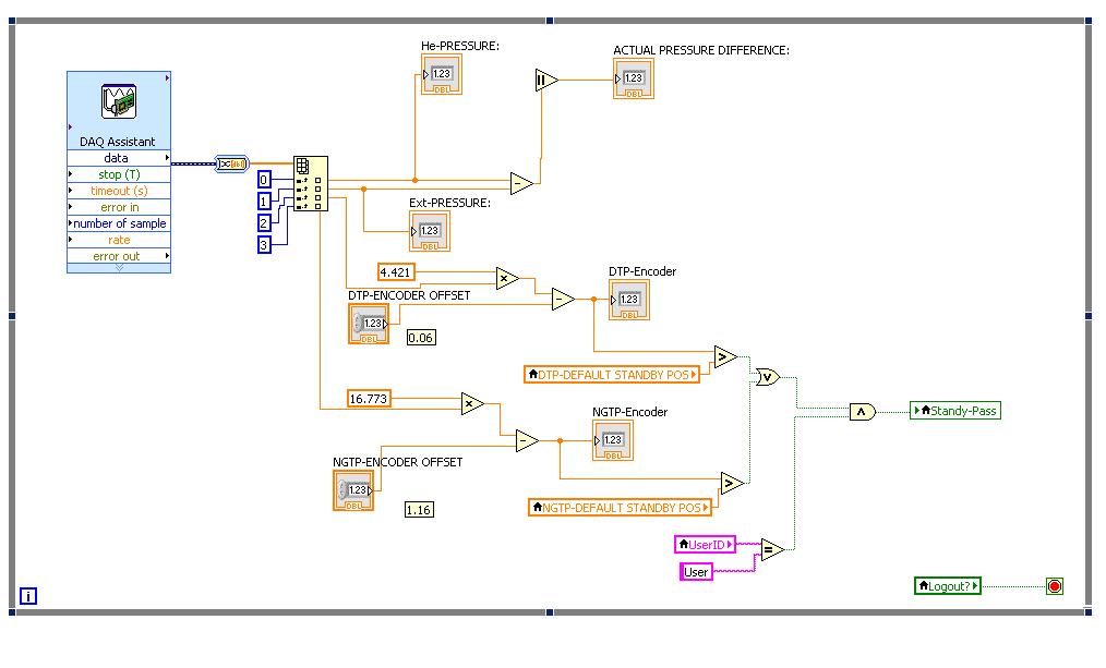
 I am receiving encoder position values from a DAQ Assistant. After either of the positions DTP or NGTP are greater than a particular value I need to fire an event. The problem is the while loop to acquire the position from the encoders is running in parallel with the main while loop for all the events. This is to enable constant updation of the position values. Below attached, is a diagram of the DAQ Assitant while loop. I tried creating an indicator and used value signalling but it did not work. I also tried using a control (button), but with the parallel loops it doesnt fire the required event. I changed it so that I have the event loop for the button inside the encoder while loop, but that just froze the while loop. I could not see any change in the position information from the encoders even when the drive was moving (information received from the drive via Profibus : this is running in a parallel while loop). Any ideas as to how to solve this? Below I have also attached the code for the main panel. MAIN PANEL.vi
-
Dear LabVIEW community! I have installed LabVIEW, v13.0f02, 32-bit on my PC. The problem, which I face, is that DAQmx Physical Channel controls, which are used in VIs inside the LV projects, sometimes don't show me the list of DAQ devices - I can't expand the list at all. I push the button to expand the list, but nothing helps. But when I create VIs outside the project, and put there DAQmx Physical Channel control - everything works well. Note: devices are simulated via MAX. Is it some kind of bug in 2013 vesrion of LabVIEW? Because while using LV 2012 I didn't have such headache. The only thing that helps now - is to restart PC (laptop) several times; b/c restart of LV doesn't help. Can anyone suggest, what it can be, and how to fix this problem? Thank you very much in advance!
-
Hey Guys, hope you have some input for me. I have a compactDAQ and I want to dynamically check the modules which are injected? Why do I want this: I have some AI and thermo modules, but not all of them are used yet. So by today there are only two modules injected, but in the future there may be more. After this I want to log some of the channels of this x-modules, so I have to create a dialoge to select the different channels of the different cards and give them names for the logging. I dont want to have a fixed order of the different modules in the chassi or something like that. Is there a way to do that? And if, how? Thanks Sagi PS: sorry for my bad english, its kinda stressy today and I have to solve this problem :/
-
Hello guys, I don't know if this is permitted here. I have a 2 year old ELVIS II+ for sale at an affordable price. Your feedbacks will be highly appreciated.
-
I have a project that I am working on that requires a very compact PC but also a PCIe DAQ card from NI. I was wondering if anyone has used an NI PCIe card through a Mini PCIe to PCIe adaptor such as: http://www.amfeltec.com/products/minipcie-to-pcie-adapter.php Would this work?
-
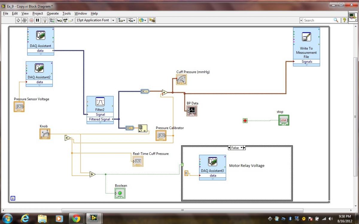
 Hi there, I am trying to implement a blood pressure (BP) monitor in Labview using NI 9239 and NI 9263. At this time, all I want is that the motor (pump) runs until a user-specified pressure is reached in the cuff. When that pressure is reached, the motor should stop but not the Labview program. As the cuff is deflating slowly through a pressure leakage valve, I want to record the pulses during cuff deflation. I used a switch statement. Gave it input from a comparator which compares the real-time pressure with user-set pressure. I put the DAQ Assistant inside this switch. I said to NI 9263, keep supplying my motor relay with rated voltage until the pressure is lower than the user-specified pressure. When this pressure exceed the user-specified pressure, I set the DAQ Assistant voltage to relay as zero, since I want the motor to stop. The above is OK. But when the cuff starts to deflate, again, the pressure becomes lower than the reference (user-defined) pressure. As a result the switch statement switches again and sends voltage to relay to run the motor again. I want something which can start off my supplying the relay with rated voltage to run the motor. As soon as real-time pressure exceeds user-defined pressure for the 1st time, I want the relay voltage to be set to zero, being unaffected by the fact that during cuff deflation, the real-time pressure will fall again below the reference pressure. I don't want the motor to run after it has pumped to a desired pressure, the first time. Thanks a lot! Saif
-
Hello, I am a research student and I am trying to get the following done: 1.A laser hits on a target. the laser point is scanned on the surface of the target. X-Y scan supported by 2 stepper motors are controlled by a labview program to move the target in X-pixels and Y-pixels. 2. The light that is reflected off the target is taken in by the detector. These analog values are converted to digital using a DSP board. This is my DAQ control board. these values are to be stored in a 2-D array and later used to form an image. My problems: I dont really understand how to control the x-y scanning sytem and how to read in the measurements and form the image. I am a beginner in labview. Any help and suggestions on this will be appreciated.
-
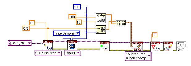
Hi, I wrote the following program trying to output a series of 100 samples of pulses whose frequency is ramping up from 10 to 100. Device: PCI-6229. I got error: -201291: Pulse specifications cannot be written to a finite counter output task on this device. I do not know what was wrong. Basically I have no idea how to use the vi, DAQmx Write: Counter Freq NSamp 1Chan or NChan I do know how to use property node to change frequency and duty cycle on the fly. However, In this particular post I would like to know how to use this NSamp VI. Thanks.